Keywords
|
| PMSG, Dynamic stability, doubly fed Induction Generator, marine-current farm, offshore wind farm, FACTS Controllers, Eigen values. |
INTRODUCTION
|
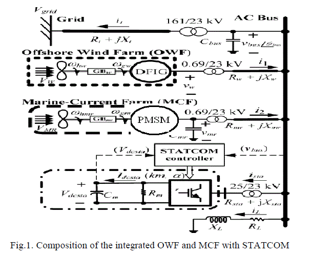
| During the last decades, Wind Energy Conversion System (WECS) has grown dramatically. Variable-speed wind Turbines (VSWTs) attract considerable interest around the world, which is one of the solutions with the highest potential to reduce wind energy cost. The VSWT systems are usually based on doubly fed induction generators (DFIGs) or permanent magnet synchronous generators (PMSGs). Basically wind farm consists of many wind turbines that are connected with each other to produce small amount of electrical power that becomes powerful after connecting with the transformer. Areas that consists of the number of wind turbines for the sake of power generation from wind and are connected with each other in the different way is called wind farm. Basically wind farm consists of many wind turbines that are connected with each other to produce small amount of electric power. Different strategies are used to build the wind farms in different locations or area. Generators driven by marine-current turbine (MCT) combined with offshore generators driven by wind turbine (WT) will become a novel scheme for energy production in the future. Since oceans cover more than 70% surface of the earth, a hybrid power generation system containing both offshore wind farm (OWF) and marine-current farm (MCF) can be extensively developed at the specific locations of the world in the future. One of the simple methods of running an OWF is to connect the output terminals of several DFIGs together and then connect to a power grid through an offshore step-up transformer and undersea cables. To run an MCF may use several Permanent Magnets synchronous generators (PMSGs) connected directly to the power grid through an offshore step-up transformer and undersea cables. |
| This paper is organized as below. The configuration and the employed models for the studied integrated OWF and MCF with STATCOM are introduced first[1]. Then, the design procedure and design results for the PID damping controller of the proposed STATCOM using pole-placement technique are depicted. Both steady-state operation points under various wind speeds and marine-current speeds and the comparative dynamic responses of the studied system with the designed PID damping controller under different operating conditions can be elaborately done here. Finally, specific important conclusions of this paper are drawn. |
MODELS OF THE OFF SHORE WIND FARM AND MARINE CURRENT FARM
|
| Figure 1, shows the structure of the studied integrated DFIG based OWF and PMSG based MCF with the proposed STATCOM. The 80MW OWF is represented by a large equivalent aggregated DFIG driven by an equivalent aggregated variable speed WT through an equivalent aggregated gearbox. The 40MW MCF is represented by a large equivalent aggregated PMSG driven by an equivalent aggregated variable speed MCT through an equivalent aggregated gearbox. The OWF, the MCF, the STATCOM and a local load are connected to an AC bus that is fed to the onshore power grid through an offshore step-up transformer and undersea cables [9]. The employed mathematical models of the studied system are described as below. |
| A. DOUBLE FED INDUCTION GENERATOR (DFIG): |
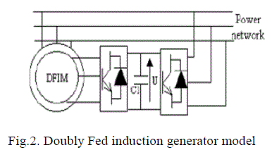
| DFIG is an abbreviation for Double Fed Induction Generator, a generating principle widely used in wind turbines. It is based on an induction generator with a multiphase wound rotor and a multiphase slip ring assembly with brushes for access to the rotor windings. It is possible to avoid the multiphase slip ring assembly, but there are problems with efficiency, cost and size. A better alternative is a brushless wound-rotor doubly-fed electric machine. Figure 2 indicates the doubly fed induction generator model. DFIG is of great advantage, and is widely used in large capacity wind turbines in recent years. |
| B. PERMANENT MAGNET SYNCHRONOUS MACHINE: |
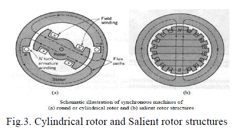
| A synchronous machine is an ac rotating machine whose speed under steady state condition is proportional to the frequency of the current in its armature. Figure 3 indicates the PMSM Cylindrical rotor and Salient rotor structures.The magnetic field created by the armature currents rotates at the same speed as that created by the field current on the rotor, which is rotating at the synchronous speed, and a steady torque results. Synchronous machines are commonly |
| used as generators especially for large power systems, such as turbine generators and hydroelectric generators in the grid power supply. Because the rotor speed is proportional to the frequency of excitation, synchronous motors can be used in situations where constant speed drive is required. Since the reactive power generated by a synchronous machine can be adjusted by controlling the magnitude of the rotor field current, unloaded synchronous machines are also often installed in power systems solely for power factor correction. The armature winding of a conventional synchronous machine [3] is almost invariably on the stator and is usually a three phase winding. The field winding is usually on rotor and excited by dc current, or permanent magnets. The dc power supply required for excitation usually is supplied through a dc generator known as exciter, machine which is often mounted on the same shaft as the synchronous. |
| C. Detailed Modelling of PMSM: |
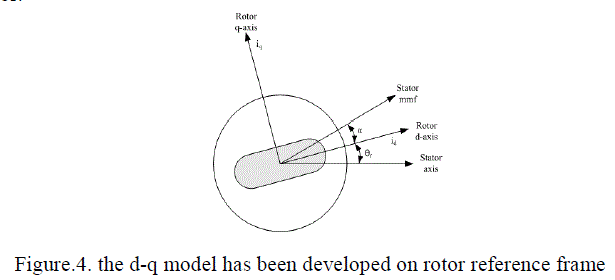
| Detailed modelling of PM motor drive system is required for proper simulation of the system. The d-q model has been developed on rotor reference frame shown in Figure 4. At any time t, the rotating rotor d-axis makes and angle with the fixed stator phase axis and rotating stator mmf makes an angle ± with the rotor d-axis [13]. Stator mmf rotates at the same speed as that of the rotor. |
| The Voltage equations are given by: |
 |
 |
| Flux Linkages are given by |
 |
 |
| Substituting equations 2 and 4 into 1 and 2 |
 |
 |
| Arranging equations 5 and 6 in matrix form |
 |
| The developed torque motor is being given by |
 |
| The mechanical torque equation is |
 |
| Solving for the rotor mechanical speed from equation 9 |
 |
| And |
 |
| In the above equations ω r is the rotor electrical speed ω m is the rotor mechanical speed. |
PITCH ANGLE CONTROL
|
| When V w is lower than the rated wind speed of the WT (VWrated ), β w =00 . When V W >VWrated , the Pitch-angle Control System of the WT activates and the pitch angle of the WT (β w ) increases. The control system structure used to generate the pitch angle reference is depicted in Figure 5. The pitch controller consists of a nonlinear feed forward path, which generates β ? and a linear feedback path, which generates Δβ [6]. |
Mass-spring-Damper System and Induction Generator
|
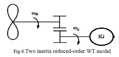
| Figure 6 shows the two-inertia reduced order equivalent mass- spring-damper model of the WT coupled to the rotor shaft of the studied wind DFIG. The effect of the equivalent gearbox (GBW ) between the WT and the DFIG has been included in this model. The per unit q-axis and d-axis voltage-current equations of an induction generator can be referred to [16], [17] and they can be used for the electrical parts of the wind DFIG and the marine current PMSG. |
MARINE-CURRENT SPEED AND MARINE-CURRENT TURBINE MODEL
|
| The MCT is assumed to be driven by tide velocities, and the current velocity is determined by spring and neap tides. The marine-current speeds are given at hourly intervals starting at 6 h before high waters and ending 6 h after. It is easy to derive a simple and practical model for marine-current speeds under the knowing tide coefficients as follows: |
 |
STATIC SYNCHRONOUS COMPENSATOR (STATCOM):
|
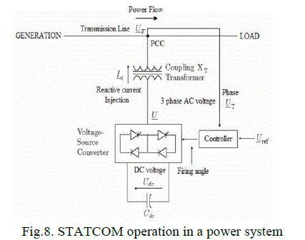
| A STATCOM is a controlled reactive-power source. It provides voltage support by generating or absorbing reactive power at the point of common coupling without the need of large external reactors or capacitor banks. Using the controller, the VSC and the coupling transformer, the STATCOM operation is illustrated in Figure 8.The one-line diagram of the studied STATCOM was shown in Figure 8. The per unit q-axis and -axis output voltages of STATCOM can be expressed by, respectively, [7]. |
 |
 |
DESIGN OF A PID DAMPING CONTROLLER FOR STATCOM USING MODAL CONTROL THEORY
|
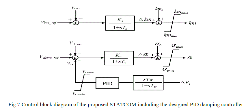
| This section presents a unified approach based on modal control theory to design the PID damping controller of the proposed STATCOM shown in Figure 7. For dynamic stability improvement of the studied system. The nonlinear system equations developed in Section II are first linearized around a nominal operating point to obtain a set of linearized system equations in matrix form of [18]. |
 |
 |
| The Eigen values and the corresponding damping ratios of the studied integrated OWF and MCF without and with the STATCOM under Vw=12 m/s and VMR=2.5 m/s are listed in the third and the fourth columns of Table II, respectively. |
STEADY STATE OPERATING ANALYSIS FOR VARIOUS CONDITIONS OF THE STUDIED SYSTEMS
|
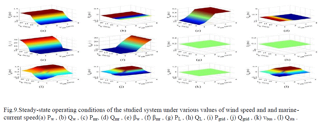
| This section presents the steady-state operating condition results of the studied system when vW is increased from 4 to 24 m/s while VMR is increased from 1 to 4 m/s. Figure 9 shows the 3-D plots for the calculated steady-state operating conditions of the studied system under the selected values for vW and VMR. The steady-state operating conditions shown in Figure 9 are analysed as below. |
SIMULATION RESULTS
|
| In this section, to show the principle of power control of PMSG-based variable-speed wind turbine connected to the grid, it is controlled in order to capture the maximum wind energy and its behaviour subjected to a variable speed wind will be illustrated using numerical simulations carried under the Matlab - SIMULINK. The damping characteristics contributed by the proposed STATCOM joined with the designed PID damping controller to getting better dynamic stability improvement of the studied system. |
| From the above simulation results it can be concluded that: |
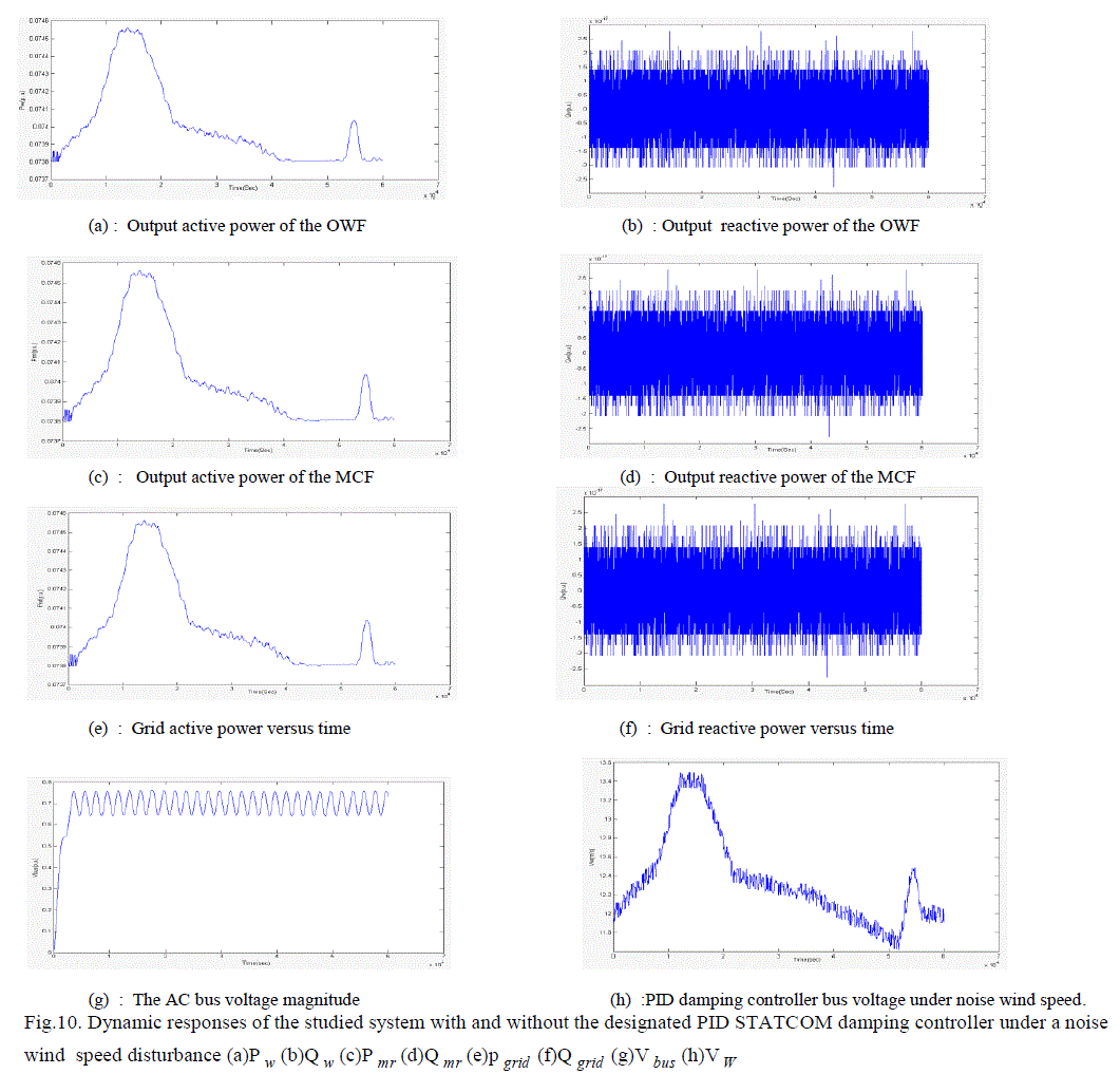
| 1) It can be seen from the dynamic response of Vbus shown Fig. 10(g) that the proposed STATCOM with the designed PID damping controller can effectively maintain the AC bus voltage at around 1.0 pu by properly adjusting ? to tune the quantity of the reactive power of the STATCOM delivered to the AC bus. |
| 2) Because the proposed STATCOM joined with the designed PID damping controller can offer adequate damping characteristics to the studied system, the oscillations of P mr , Wrmr , V MR , Vbus due to the random noise wind speed disturbance can be fast damped, and they have the smallest amplitudes in three curves. |
| 3) The amplitudes of the active power delivered to the Power grid (P grid ) shown in Fig. 10(e) and the active Power generated by the SCIG of the MCF shown in Fig.10(c) can be slightly reduced and the absorbed reactive Power from the power grid (Q grid ) shown in Fig. 10(f) can be decreased when the STATCOM joined with the PID Controller is included in the studied system. |
| 4) The generated active power of the DFIG P w shown in Fig. 10(a) is not affected by the addition of the STATCOM with the PID controller. |
CONCLUSION
|
| The main focus of this paper has been the study and control of a direct-driven PMSG used in variable speed windenergy system connected to the grid. This wind system was modelled using d-q rotor reference frame and is interfaced with the power system through an inverter and a filter modelled in the power system reference frame. This paper has presented the dynamic stability improvement of an integrated OWF and MCF using a STATCOM. A PID damping controller has been designed for the STATCOM by using a unified approach based on pole-assignment approach. Eigen value calculations and time domain simulations of the studied system subject to a noise wind-speed disturbance, a marine current speed disturbance, and a three-phase short circuit fault at the grid have been systematically performed to demonstrate the effectiveness of the proposed STATCOM joined with the Designed PID damping controller on suppressing voltage fluctuation of the studied system and improving system dynamic stability under different operating conditions. It can be concluded from the simulation results that the proposed STATCOM joined with the designed PID damping controller is capable of improving the performance of the studied integrated OWF and MCF under different operating conditions. |
Tables at a glance
|
 |
 |
| Table 1 |
Table 2 |
|
| |
Figures at a glance
|
 |
 |
 |
 |
 |
| Figure 1 |
Figure 2 |
Figure 3 |
Figure 4 |
Figure 5 |
 |
 |
 |
 |
 |
| Figure 6 |
Figure 7 |
Figure 8 |
Figure 9 |
Figure 10 |
|
| |
References
|
- S. E. B. Elghali, R. Balme, K. L. Saux, M. E. H. Benbouzid, J. F. Charpentier, and F. Hauville, “A simulation model for the evaluation of the electrical power potential harnessed by a marine current turbine,” IEEE J. Ocean. Eng., vol. 32, no. 4, pp. 786–797, Oct. 2007.
- W. M. J. Batten, A. S. Bahaj, A. F. Molland, and J. R. Chaplin, “Hydro-dynamics of marine current turbines,” Renewable Energy, vol. 31, no. 2, pp. 249–256, Feb. 2006.
- L. Myers and A. S. Bahaj, “Simulated electrical power potential harnessed by marine current turbine arrays in the Alderney race,” Renewable Energy, vol. 30, no. 11, pp. 1713–1731, Sep. 2005.
- H. Chong, A. Q. Huang, M. E. Baran, S. Bhattacharya, W. Litzenberger, L. Anderson, A. L. Johnson, and A. A. Edris, “STATCOM impact study on the integration of a large wind farm into a weak loop power system,” IEEE Trans. Energy Convers., vol. 23, no. 1, pp. 226–233, >Mar. 2008.
- H. Gaztanaga, I. Etxeberria-Otadui, D. Ocnasu, and S. Bacha, “Real-time analysis of the transient response improvement of fixed-speed wind farms by using a reduced-scale STATCOM prototype,” IEEE Trans. Power Syst., vol. 22, no. 2, pp. 658–666, May 2007.
- T. Y. Lee, “Operating schedule of battery energy storage system in a time-of-use rate industrial user with wind turbine generators: A multipass iteration particle swarm optimization,” IEEE Trans. Energy Convers., vol. 22, no. 3, pp. 774–782, Sep. 2007.
- R. S. Bhatia, S. P. Jain, D. K. Jain, and B. Singh, “Battery energy storage system for power conditioning of renewable energy sources,” in Proc.Int. Conf. Power Electron. Drive Syst., Jan. 2006, vol. 1, pp. 501–506.
- D. J. Swider, “Compressed air energy storage in an electricity system with significant wind power generation,” IEEE Trans. Energy Convers., vol. 22, no. 1, pp. 95–102, Mar. 2007.
- S. Nomura, Y. Ohata, T. Hagita, H. Tsutsui, S. Tsuji-Iio, and R. Shimada, “Wind farms linked by SMES systems,” IEEE Trans. Appl. Supercond., vol. 15, no. 2, pp. 1951–1954, Jun. 2005.
- K. Shikimachi, H. Moriguchi, N. Hirano, S. Nagaya, T. Ito, J. Inagaki, S. Hanai, M. Takahashi, and T. Kurusu, “Development of MVA class HTS SMES system for bridging instantaneous voltage dips,” IEEE Trans. Appl. Supercond., vol. 15, no. 2, pp. 1931–1934, Jun. 2005.
- M. G. Rabbani, J. B. X. Devotta, and S. Elangovan, “Application of simultaneous active and reactive power modulation of SMES unit under unequal a-mode for power system stabilization,” IEEE Trans. Power Syst., vol. 14, no. 2, pp. 547–552, May 1999.
- Q. Jiang and M. F. Conlon, “The power regulation of a PWM type super-conducting magnetic energy storage unit,” IEEE Trans. Energy Convers., vol. 11, no. 1, pp. 168–174, Mar. 1996.
- L. Chen, Y. Liu, A. B. Arsoy, P. F. Ribeiro, M. Steurer, and M. R. Iravani, “Detailed modeling of superconducting magnetic energy storage (SMES) system,” IEEE Trans. Power Del., vol. 21, no. 2, pp. 699–710, Apr. 2006.
- S. C. Tripathy and K. P. Juengst, “Sampled data automatic generation control with superconducting magnetic energy storage in power systems,” IEEE Trans. Energy Convers., vol. 12, no. 2, pp. 187–192, Jun. 1997.
- M. Steurer, C. A. Luongo, P. R. Ribeiro, and S. Eckroad, “Interaction between a superconducting coil and the power electronics interface on> a 100 MJ SMES system,” IEEE Trans. Appl. Supercond., vol. 13, no. 2, pp. 1806–1809, Jun. 2003.
- B. C. Pal, “Robust pole placement versus root-locus approach in the con-text of damping interarea oscillations in power systems,” Proc. Inst. Electr.Eng. Gener.Transmiss.Distrib., vol. 149, no. 6, pp. 739–745, Nov. 2002.
- C. T. Hsu, “Enhancement of transient stability of an industrial cogeneration system with superconducting magnetic energy storage unit,” IEEETrans. Energy Convers., vol. 17, no. 4, pp. 445–452, Dec. 2002.
- Y. Mitani, K. Tsuji, and Y. Murakami, “Application of superconducting magnet energy storage to improve power system dynamicperformance,”IEEE Trans. Power Syst., vol. 3, no. 4, pp. 1418–1425, Nov. 1988.
- Y. L. Tan and Y. Wang, “Augmentation of transient stability using a superconducting coil and adaptive nonlinear control,” IEEE Trans. Power Syst., vol. 13, no. 2, pp. 361–366, May 1998.
- C. Rehtanz, “Systemic use of multifunctional SMES in electric power systems,” IEEE Trans. Power Syst., vol. 14, no. 4, pp. 1422–1427, Nov. 1999.
- J. Yu, X. Duan, Y. J. Tang, and P. Yuan, “Control scheme studies of voltage source type superconducting magnetic energy storage (SMES) under asymmetrical voltage,” IEEE Trans. Appl. Supercond., vol. 12, no. 1, pp. 750–753, Mar. 2002.
|