Keywords
|
| AODV, Average End-to-end delay, IEEE 802.11 standard, IEEE 802.11e standard, QualNet |
INTRODUCTION
|
| The advancement in information technology and the need for large-scale communication infrastructures has triggered the area of Wireless sensor networks (WSNs). Mobile ad-hoc network (MANET) is a network of wireless mobile nodes which communicate with each other without any centralized control or established infrastructure. Routing is the process of selecting paths in a network along which data is to be sent, it is a critical task in MANET where the nodes are mobile. Dynamic and reliable routing protocols are required in the ad-hoc wireless networks, as they have no infrastructure (base station) and their network topology changes. There are various protocols for handling the routing problem in the ad-hoc wireless network environment [1]. |
| IEEE 802.11 based wireless local area networks have become more and more popular due to low cost and easy deployment, they can only provide best effort services and do not have quality of service supports for multimedia applications. Recently, a new standard, IEEE 802.11e, has been proposed, which introduces a so-called hybrid coordination function (HCF) containing two medium access mechanisms: contention based channel access and controlled channel access. We illustrate that the 802.11e standard provides a very powerful platform for QoS supports in WLANs. The IEEE 802.11 standard adopts the 802.11e as the medium access protocol and 802.11n-based products, which utilize multiple-input-multiple-output (MIMO) transmission systems. The key idea of the scheme, which is called MIMO-based EDCF (M-EDCF), is the sharing of the spatial channels during the medium contention period, i.e., instead of accessing the medium using all the spatial channels, the accessing nodes use a subset of the available spatial channels. As the number of concurrent spatial channels used is less than or equal to the spatial degree of freedom, receivers can decode the transmitted signals of different medium access contenders and then coordinate their responses to avoid potential collisions. The spatial channel sharing also enables transmitters to sense the medium and terminate if they detect other ongoing medium access attempts [2] [9]. |
| In recent years, the progress of communication technology has made wireless devices smaller, less expensive and more powerful. The rapid technology advance has provoked great growth in mobile devices connected to the Internet. Hence various wireless network technologies such as 3G, 4G of cellular network, ad-hoc, IEEE 802.11 based wireless local area network (WLAN) and Bluetooth are used. IEEE 802.15.4 is a very important technology of ubiquitous WSN. In MANET links between the nodes can change during time, new nodes can join the network and other nodes can leave it. The set of applications for MANETs is various, ranging from small static networks that are constrained by power sources to large-scale, mobile, highly dynamic networks. MANET is expected to be of larger size than the radio range of the wireless antennas, because of this fact it could be necessary to route the traffic through a multi-hop path to give two nodes the ability to communicate. Unfixed topology in ad-hoc networks resulting in finding the delivery path dynamically, maintain the integrity and stability of the path during data delivery process. This ensures the data packets are transferred to the destination node completely. The traditional routing mechanisms and protocols of wired network are inapplicable to ad-hoc networks, which initiated the need to use a dynamic routing mechanism in ad-hoc network. In this paper we focus on the performance of AODV and DSR reactive routing protocol using QualNet 5.0 simulator for different IEEE standards such as 802.11 MAC, PHY and Energy model WLAN standards [2] [9]. The rest of the paper is organized as follows. The overview of IEEE 802.11 PHY/MAC and Energy Models are summarized in section II. Brief description of AODV and DSR reactive Routing Protocol discussed in section III and in section IV Implementation of related work is discussed. The simulation results are discussed in section V and conclusion in section VI. |
OVERVIEW OF IEEE 802.11 PHY/MAC AND ENERGY MODELS
|
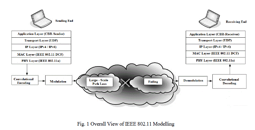
| In 1997, IEEE standardized the first Wireless Standard: 802.11. This comprised both Medium Access Control (MAC) layer and Physical layer. While the IEEE 802.11 standard and all the later extensions provide extensive information regarding different aspects of the communication, we do not intend to summarize all that information in this introduction. In the coming three subsections, we briefly mention the concepts in MAC layer, Physical layer, Propagation Model and Energy Model for an extensive behaviour of the standard (MAC and PHY layers) [2]. |
| A. IEEE 802.11 Overview: |
| IEEE 802.11: It is a modification to the IEEE 802.11 specification that added a higher data rate of up to 54 Mbit/s using the 5 GHz band. It has seen extensive worldwide implementation, particularly within the commercial and business workspace. On the other hand, OFDM has fundamental propagation advantages when in a high multipath environment, such as an indoor office, and the higher frequencies enable the building of smaller antennas with higher RF system gain which counteract the disadvantage of a higher band of operation. The increased number of usable channels and the near absence of other interfering systems (microwave ovens, cordless phones, baby monitors) give 802.11 significant aggregate bandwidth and reliability advantages over 802.11b/g [2]. |
| B. IEEE 802.11 MAC Layer: |
| MAC layer, as its primary purpose, has the functionality of providing reliable data delivery mechanism over the unreliable wireless air interface. It is the layer who manages station access to the shared wireless medium. The original standard utilizes Carrier Sense Medium Access with Collision Avoidance (CSMA/CA) as the access mechanism. However, this access method wastes a significant percentage of channel capacity, but, it is a necessary feature to provide reliability in data transmission. Among many other features, it also supports Request-To-Send (RTS) and Clear-To-Send (CTS) mechanism to address the case where two nodes are not aware of the presence of each other and want to communicate with a node which is in transmission range of both. RTS/CTS mechanism helps to avoid the corruption of the packets in the above scenario [2]. |
| 1) Distributed Coordination Function (DCF): |
| It is the basic 802.11 MAC layer. DCF uses the above mentioned CSMA/CA method to share the medium between the stations. It may optionally use the RTS/CTS method as well. Under this method, collision rate is relatively high and there is no concept of Quality of Service (QoS) in the network [2]. |
| 2) Point Coordination Function (PCF): |
| It is another basic coordination function which is defined only in infrastructure mode, where stations are connected to an access point. Access point is the element in control of access in the network and it uses two periods to enforce its policies. There is a Contention Period, in which, DCF method is used. The second period is the Contention Free Period, in which AP basically allows stations, by sending them a special authorization, to send packets. IEEE 802.11 standard addressed the existing limitations in DCF and PCF. It particularly addressed the problem of QoS provisioning in the network by introducing a new coordination function: Hybrid Coordination Function – HCF [3]. |
| C. IEEE 802.11 PHY Layer: |
| IEEE 802.11 Physical layer is the interface between MAC layer and the air interface. The frame exchange between Physical layer and MAC is under the control of Physical Layer Convergence Procedure (PLCP). Physical Layer is the entity in charge of actual transmission using different modulation schemes over the air interface. It also informs the MAC layer about the activity status of the medium. Currently, there are four standards defining the physical layer: IEEE 802.11a, 802.11b, 802.11g and 802.11n. Among these, IEEE 802.11n is the newest which is still under standardization. It utilizes Multiple-Input-Multiple- Output (MIMO) technology to achieve significantly higher rates. These Physical Layer standards define their operating frequency band, number of available channels, possible transmission rates, modulation and Forward Error Correction (FEC) coding schemes. Propagation models are not part of the Physical Layer standards; however, as mentioned before, they form an integral part of physical layer implementation in the simulators [3] [4]. |
| D. Propagation Models: |
| In this section, we explore both concepts of Large-scale Path Loss and Fading. We introduce three models of Large-scale Path Loss which account for the large-scale attenuation of signal based on distance: Free-Space, Two-Ray and Lognormal Shadowing. As will be presented hereafter, however, the level of sophistication and the inclusiveness of the models increase from the simple model of Free-space to the more realistic model of Shadowing. On the other hand, Fading is the phenomenon responsible for rapid fluctuations of signal over a short period of time or distance [5]. |
| 1) Free-Space Model: |
| This model is used to predict the signal strength when the transmitter and the receiver have a clear, unobstructed line-of sight (LOS) path between them [5]. It predicts that the received power decays as a function of Transmitter-Receiver distance rose to some power, typically to the second power. |
| 2) Two-Ray Model: |
| This model, which is a more realistic model than the Free-Space model, addresses the case when we consider a ground reflected propagation path between transmitter and receiver, in addition to the direct LOS path. This model is especially useful for predicting the received power at large distances from the transmitter and when the transmitter is installed relatively high above the ground [11]. |
| 3) Log-normal Shadowing Model: |
| The empirical approach for deriving radio propagation models is based on fitting curves or analytical expressions that recreate a set of measured data. Adopting this approach has the advantage of taking into account all the known and unknown phenomena in channel modelling [5]. A widely-used model in this category is Log-normal Shadowing. In this model, power decreases logarithmically with distance. The average loss for a given distance is expressed using a Path Loss Exponent. For taking into account the fact that surrounding environmental clutter can be very different at various locations having the same Transmitter-Receiver distance, another parameter is incorporated in the calculation of path loss. According to measurement results, this parameter, called shadowing hereafter, is a zero-mean Gaussian distributed random variable (in dB) with a standard deviation, also expressed in dB. Shadowing accounts for the fact that measured data are sometimes significantly different from the average power at a given distance from the transmitter [9]. |
| 4) Fading Model: |
| The term fading is used to describe the rapid fluctuations of the amplitudes, phases, or multipath delays of a signal over a short period of time or distance. It is caused by interference between multiple versions of the transmitted signal which arrive at the receiver at slightly different times [7]. Hence, the resulting signal at the receiver may have a wide-varying amplitude and phase. In short, the effects of multipath are rapid changes in signal strength over a small travel distance or time interval, random frequency modulation due to varying Doppler shifts on different multipath signals and time dispersion caused by multipath propagation delays. The multipath components combine vectorially at the receiver which causes the signal to distort, to fade or even to strengthen at times. Type of fading experienced by the signal going through a channel depends on the nature of the signal and the characteristics of the channel. If the bandwidth of the signal is smaller than the bandwidth of the channel, or equally in the time domain, the delay spread of the channel is smaller than the symbol period, the fading is considered to be flat. Otherwise, the fading channel is considered to be frequency selective. Rayleigh distribution is commonly used to describe the statistical time varying nature of the received envelope of a flat fading signal, or the envelope of an individual multipath component [7] [9]. |
AODV AND DSR REACTIVE ROUTING PROTOCOL
|
| A. Dynamic Source Routing (DSR) Protocol |
| The Dynamic Source Routing Protocol [8] is an on-demand routing protocol which is based on the concept of source routing. In source routing, a sender node specifies in the packet header, the complete list of nodes that the packet must pass through to and reach the destination node. This essentially means that every node just needs to forward the packet to its next hop specified in the header and need not check its routing table as in table-driven routing protocols. The DSR protocol works in two phases as described below. |
| 1) Route Discovery: |
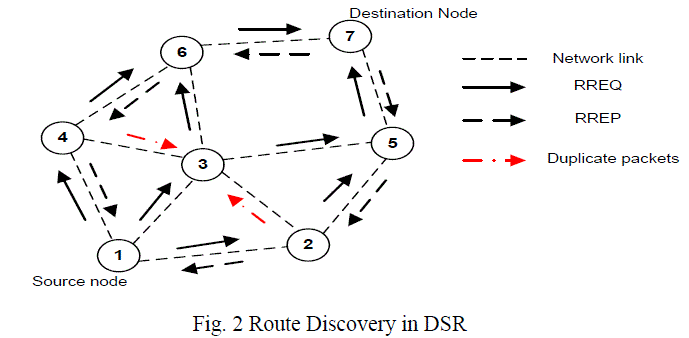
| In the route discovery phase, the source node establishes a route by broadcasting route request (RREQ) packets to all its neighbors. Each neighboring node, in turn rebroadcasts the packets to its neighbors if it has not already done so, or if it is not the destination node, provided that the TTL (Time to Live) counter is greater than zero. Further, request ids are used to determine if a particular route request has been previously received by the node. This reply packet contains the route to that destination. Fig.2 shows an example of the route discovery mechanism. When node 1 wants to communicate with node 7, it initiates a route discovery mechanism and broadcasts request packet RREQ to its neighboring nodes 2, 3 and 4 as shown. However, node 3 also receives the broadcast packets from nodes 4 and 2 with the same pair. It drops both of them and broadcasts the other packet to its neighbors. The other nodes follow the same procedure. When the packet reaches node 7, it inserts its own address and reverses the route in the record and unicasts it back on the reverse path to the destination. |
| 2) Route Maintenance: |
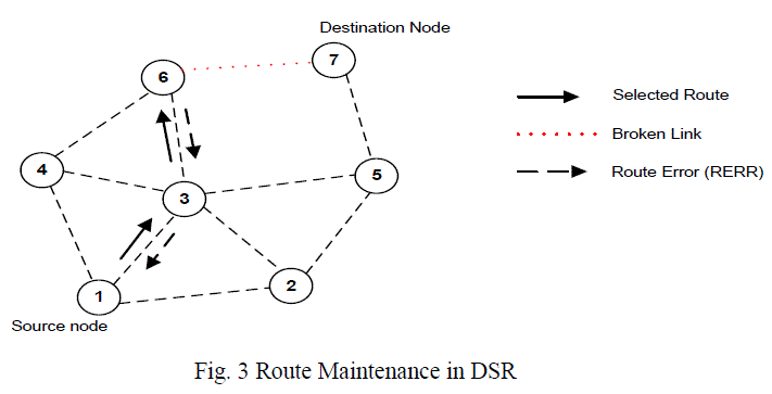
| The route maintenance phase is carried out whenever there is a broken link between two nodes. A failed link can be detected by a node by either passively monitoring in promiscuous mode or actively monitoring the link. As shown in Figure 3, when an intermediate node in the path moves away, causing a wireless link to break (6-7), a route error packet (RERR) is sent by the intermediate node back to the originating node. The source node re-initiates the route discovery procedure to find a new route to the destination. It also removes any route entries it may have in its cache to the destination node. |
| DSR benefits from source routing since the intermediate nodes need not maintain up-to-date routing information in order to route the packets that they forward. There is also no need for any periodic routing advertisement messages. However, as size of the network increases, the routing overhead increases since each packet has to carry the entire route to the destination with it. The use of route caches is a good mechanism to reduce the propagation delay but overuse of the cache may result in poor performance [8]. The disadvantage of DSR is that whenever there is a link break, the RERR packet propagates to the original source, which in turn initiates a new route discovery process. Thus the link is not repaired locally. Several Optimizations to DSR are possible such as non- propagating route requests (when sending RREQ, nodes set the hop limit to one preventing them from re-broadcasting), gratuitous route replies (when a node over hears a packet with its own address listed in the header, it sends a RREP to the originating node bypassing the preceding hops), etc. A detailed explanation of DSR optimizations can be found in [8] [9]. |
| B. Ad hoc on-demand Distance Vector (AODV) Routing Protocol: |
| The Ad hoc on-demand Distance Vector routing protocol [8] inherits the good features of both DSDV and DSR. The AODV routing protocol uses a reactive approach to finding routes and a proactive approach for identifying the most recent path. More specifically, it finds routes using the route discovery process similar to DSR and uses destination sequence numbers to compute fresh routes. The two phases are discussed in more detail; |
| 1) Route Discovery: |
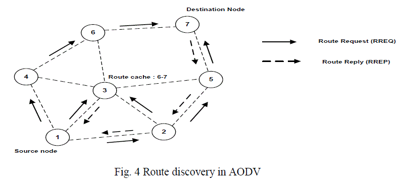
| During the route discovery process, the source node broadcasts RREQ packets similar to DSR. The RREQ packet contains the source identifier, the destination identifier, the source sequence number, the destination sequence number, the broadcast identifier. When an intermediate node receives a RREQ packet, it either forwards it or prepares a Route Reply (RREP) packet if it has a valid route to the destination in its cache. Whenever a RREP packet is received by a node, it stores the information of the previous node in order to forward the packet to it as the next hop towards the destination. This acts as a “forward pointer” to the destination node. Thus each node maintains only the next hop information unlike source routing in which all the intermediate nodes on the route towards the destination are stored. Fig.4 shows an example of route discovery mechanism in AODV. Let us suppose that node 1 wants to send a data packet to node 7 but it doesn’t have a route in its cache. Then it initiates a route discovery process by broadcasting a RREQ packet to all its neighboring nodes [9]. |
| When nodes 4, 3 and 2 receive this, they check their route caches to see if they already have a route. If they don’t have a route, they forward it to their neighbors, else the destination sequence number in the RREQ packet is compared with the destination sequence in its corresponding entry in route cache. If the destination sequence in RREQ packet is greater, then it replies to the source node with a RREP packet containing the route to the destination. In fig. 4 node 3 has a route to 7 in its cache and its destination sequence is higher compared to that in RREQ packet. So, it sends a RREP back to the source node 1. Thus the path 1-3-6-7 is stored in node 1. The destination node also sends a RREP back to the source. For example, one possible route is 1-2-5-7. The intermediate nodes on the path from source to destination update their routing tables with the latest destination sequence in the RREP packet. |
| 2) Route Maintenance: |
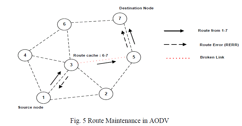
| The route maintenance mechanism works as follows; whenever a node detects a link break by link layer acknowledgements or HELLO beacons, the source and end nodes are notified by propagating an RERR packet similar to DSR. This is shown in Fig. 5 If the link between nodes 3 and 5 breaks on the path 1-3-5-7, and then both 5 and 3 will send RERR packets to notify the source and destination nodes. One optimization possible in AODV route maintenance is to use an expanding ring search to control the flood of RREQ and discover routes to unknown destinations [10]. The main advantage of AODV is that it avoids source routing thereby reducing the routing overload in large networks. Further, it also provides destination sequence numbers which allows the nodes to have more up-to-date routes. However, AODV requires bidirectional links and periodic link layer acknowledgements to detect broken links. Further, it has to maintain routing tables for route maintenance unlike DSR. |
| D. Energy Consumption Model: |
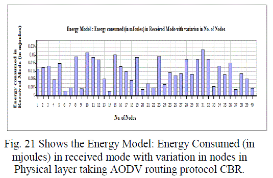
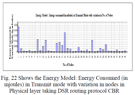
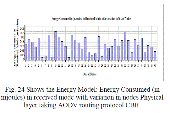
| In our work we have assuming an energy supply of 5V. The value corresponds to a 2,400MHz Wave LAN implementation of IEEE 802.11. When a node sends and receives a packet, the network interfaces of the node, decrements the available energy according to the following parameters: characteristics of network, the size of the packets and the used bandwidth. The following equations represent the energy used (in Joules) when a packet is transmitted or received; packet size is represented in bits [12]: |
| Energy Tx = (Transmitted Power x Packet Size) / 2 x 10⁶ |
| Energy Rx = (Receiving Power x Packet Size) / 2 x 10⁶ |
| Although actual equipment consume energy not only when sending and receiving but also while listening, we assume in our model that the listen operation is energy free, since all the evaluated ad hoc routing protocols will have similar energy consumption due to the node idle time. Finally, note that when a packet is transmitted, a percentage of the consumed energy represents the Radio Frequency (RF) energy. This energy is used for the propagation model in QualNet 5.0 to determine the energy with which the neighbours’ interface nodes will receive the packet, and consequently determine the successful or wrong packet reception. In our simulation we maintain this RF values in 271.8 mW, which corresponds to the RF energy required to model a radio range of 300 meters [6] [13]. |
IMPLEMENTATION OF RELATED WORK
|
| Our aim of these simulations was to analyze the selected routing protocols (DSR and AODV) for their efficiency in terms of energy, overhead, throughput, average jitter as well as network life time [6]. The basic methodology consists of simulating with a basic scenario and then by varying selected parameters, simulates the generated scenarios. The selected parameters are sources, pause time, nodes, area, sending rate and mobility speed. In the simulation the nodes move according to random way point mobility model. Each node starts moving from its initial position toward random position with the speed varying between 0 and maximum speed and when reaches the target position stay there for pause time and again start its journey towards next chosen random target. The traffic sources used in the simulations generated constant bit rate (CBR) data traffic. The TCP sources are not being chosen because it adapts to the load of the network. For the same data traffic and movement scenario, the time of sending the packet of a node will be different in case of TCP, hence will become difficult to compare the performance of different protocols. The energy model taken is as used by. The values used correspond to 2,400 MHZ Wave LAN implementation of IEEE 802.11. The radio frequency value is set as 0.2818 W for transmission range of 300 m. The following equations are used to compute energy required to transmit/ receive the packets of given size [6]: |
| A. Simulation Scenario-A: |
| The performance of AODV routing protocol is evaluated by keeping the network speed (10mps) and pause time (30s) constant, while the network size (number of mobile nodes) is varied from 10 to 50 nodes. Table 2 shows the simulation parameters used in the evaluation. |
| B. Simulation Scenario-B: |
| The performance of DSR routing protocol is evaluated by keeping the network speed (10mps) and pause time (30s) constant, while the network size (number of mobile nodes) is varied from 10 to 50 nodes. Table 2 shows the simulation parameters used in the evaluation [6]. |
SIMULATION AND RESULTS
|
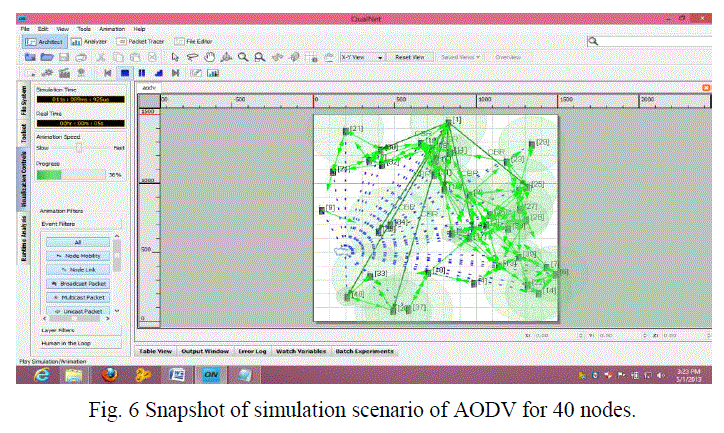
| The overall goal of this simulation study is to evaluate the performance of reactive routing protocol AODV and DSR for different node density and various speeds of nodes for both IEEE 802.11 and IEEE 802.15.4 standards. The simulations have been performed using QualNet 5.0 network simulator software that provides scalable simulations of Wireless Networks. The simulation is carried out in two simulation scenarios A and B. |
| C. Average Jitter, Throughput and Average End to End Delay (Application Layer): |
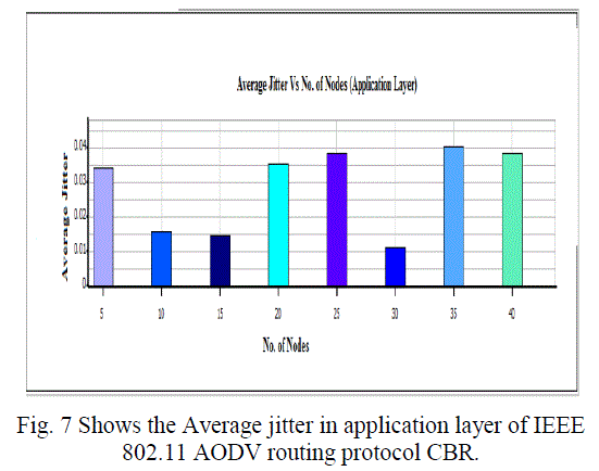
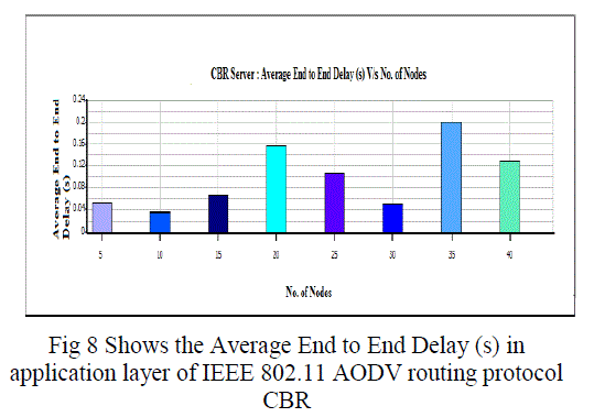
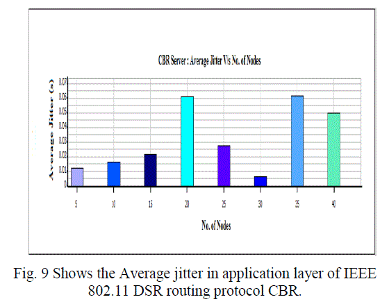
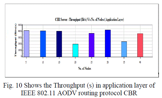
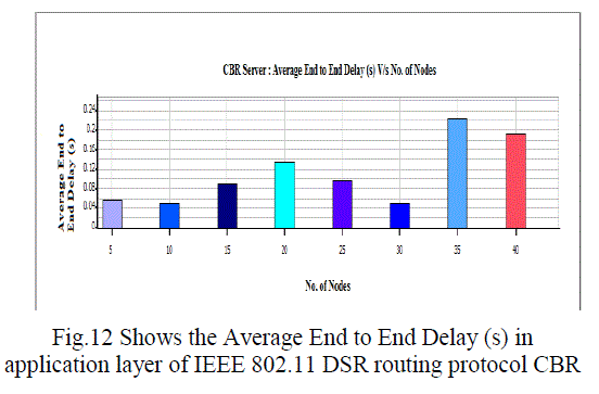
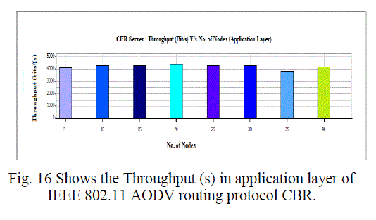
| Overall throughput is calculated as the total number of bytes (including RTS and CTS control packets) transmitted in the network in one second. The overall throughput of AODV and DSR is shown in Fig. We observe that the throughput for IEEE 802.11 compares poorly with the other schemes for all test loads. Hence a lot of packets are dropped. IEEE 802.11 therefore does not perform well for real time traffic in multi-hop ad hoc networks. The end-to-end delay is the total time that a packet takes to travel from source to its final destination. The average, minimum and maximum end-to-end delays for AODV and DSR are shown in Fig.7 -10. |
CONCLUSION
|
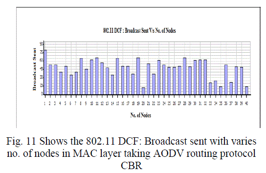
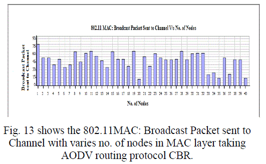
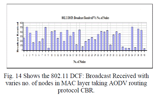
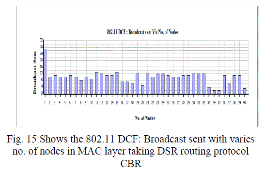
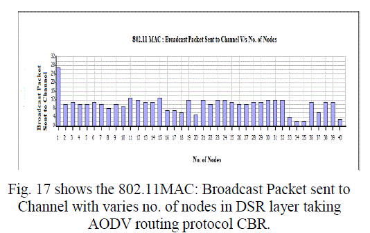
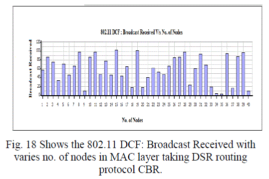
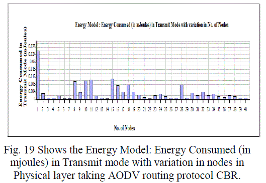
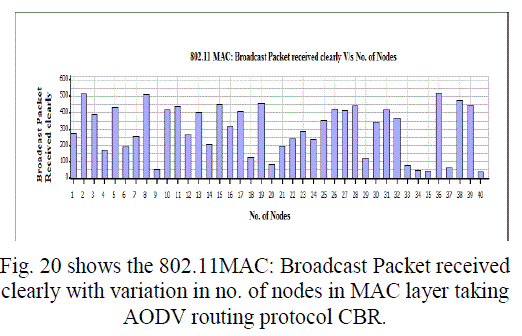
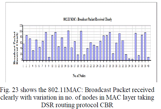
| In this paper, we analyzed the state of IEEE 802.11 implementations in the widely-used open-source network simulators. As mentioned previous to, for evaluating IEEE 802.11 network mechanisms, one needs to have proper modeling and realistic implementation of IEEE 802.11 MAC and physical layers along with all the necessary propagation models using QualNet simulator. A range of simulations were executed to test the MMMP performance and the energy efficiency of its features under varying network load and nodes conditions. Our proposed investigation work performed IEEE 802.11 in terms of throughput for all traffic load conditions. The propagation model, Physical layer and Energy model depends on the environment in which we assume our network parameters which has been implemented. The performance of AODV and DSR reactive routing protocol is studied by considering IEEE 802.11 and standards for the metrics average end to end delay, throughput, 802.11 DCF: broadcast send and received, 802.11MAC: broadcast packet sent to channel and received and Energy Model: energy consumed in transmit and received mode by varying network size and output shown above in graphical representation. |
Tables at a glance
|
 |
 |
| Table 1 |
Table 2 |
|
| |
Figures at a glance
|
 |
 |
 |
 |
 |
| Figure 1 |
Figure 2 |
Figure 3 |
Figure 4 |
Figure 5 |
 |
 |
 |
 |
 |
| Figure 6 |
Figure 7 |
Figure 8 |
Figure 9 |
Figure 10 |
 |
 |
 |
 |
 |
| Figure 11 |
Figure 12 |
Figure 13 |
Figure 14 |
Figure 15 |
 |
 |
 |
 |
 |
| Figure 16 |
Figure 17 |
Figure 18 |
Figure 19 |
Figure 20 |
 |
 |
 |
 |
| Figure 21 |
Figure 22 |
Figure 23 |
Figure 24 |
|
| |
References
|
- M.Subramanyabhat, D.Swetha and J.T. Devaraju, 2011. “A Performance Study of Proactive, Reactive and Hybrid Routing Protocols using Qualnet Simulator”, IJCA (0975 - 8887). Volume 28.No.5. August 2011.
- Mayank Mishra and AnirudhaSahoo. “An 802.11 based MAC Protocol for Providing QoS to Real Time Applications”. IEEE 10th InternationalConference on Information Technology, 6:615-619, 2007.
- Z. Ling, A. L. Ananda and L. Jacob, “A QoS Enabled MAC Protocol for Multi-hop Ad Hoc Wireless Networks,” Proc. IEEE International PerformanceComputing and Communication Conf., April 2003.
- Jeffrey W. Robinson, Student , and Tejinder S. Randhawa. Saturation “Throughput Analysis of IEEE 802.11e Enhanced Distributed CoordinationFunction”, IEEE journal on selected areas communications, 22(5): June 2004.
- Royer, E.M., 1999, “A review of current routing protocols for ad hoc mobile wireless networks”, IEEE Personal Communications, pp: 46-55.
- QualNet documentation, “QualNet 5.0.2 Model Library: Advanced Wireless”; Available: http://www.scalablenetworks.
- S.P.Setty, K. NarasimhaRaju and K. Naresh Kumar- “Performance Evaluation of AODV in different environments” - International Journal of Engineering Science and Technology, Vol. 2(7), 2010, 2976-2981.
- Perkins C. and Royer E.M., “Ad-Hoc on-Demand Distance Vector Routing,” in proceedings of the 2ndIEEE Workshop on Mobile Computing Systemsand Applications, New Orleans, LA,pp.90- 100,February 1999.
- J. Zheng and Myung J. Lee, "A comprehensive performance study of IEEE 802.15.4," Sensor Network Operations Book, IEEE Press, Chapter 4, 218-237,2006.
- P. Mahapatra, J. Li and C. Gui, "QoS in Mobile Ad Hoc Networks", IEEE Wireless Communications, June 2003.
- H. Wu, Y. Liu, Q. Zhang and Z.-L. Zhang, "SoftMAC: Layer 2.5 Collaborative MAC for Multimedia Support in Multihop Wireless Networks," IEEETrans. Mobile Computing, vol. 6(1), pp. 12-25, Jan. 2007.
- G. Lu, B. Krishnamachari and C.S. Raghavendra, “Performance evaluation of the IEEE802.15.4 MAC for low-rate low power wireless networks," inProceedings of the 23rd IEEE International Performance Computing and Communications Conference (IPCCC '04), Pages 701-706, USA, April 2004.
- C. Perkins, E.M. Royer, S.R. Das, and M.K.Marina, “Comparison of Two On-demand Routing Protocols for Ad-Hoc Personal Communications”, pp. 16-28, feb. 2001.
- T.BhimarjunaReddy,I.Karthigeyan,B.S.Manoj,C.Siva Ram Murthy,“Quality of service provisioning in ad hoc wireless networks: a survey of issues andsolution”. Journal of ad hoc networks, 4(1):83-124, 2006.
|