Keywords
|
| Telecommunication network,Call failure, SS7, NS2 |
INTRODUCTION
|
| In Telecommunication SS7 signalling traces analysed by manually which is time consuming and then more man power is needed. These bulk traces analysed case by case basis and when there is a complaint. As per telecommunication statistics, telephone subscribers are 995.9 million. The usage of telephone is increasing gradually, so that routing and traffic management of network is very important. Because vendors of telecommunication maintain to stand in people mind. |
| But presently SS7 traces analysed manually as per user complaints. But some users do not complaint to the network, their switch over to another network. That’s why network efficiency ratio reduced and revenue loss occurred. |
BASICS OF SS7
|
| Signalling system 7 is architecture for performing out-of-band signalling in support of the call-establishment, billing, routing, and information-exchange functions of the public switched telephone network (PSTN).it defines functions to be performed by a signalling system network and protocol to enable their performance. SS7 can also be defined as a set of telephony signalling protocols which are used to set up most of the world’s public switched telephone network telephone calls. |
| The main purpose of the protocol is tearing down the telephone calls. Other use includes number translation, prepaid billing mechanisms, short message service (SMS), and a variety of other mass market services. It is usually referenced as signalling system No.7 or Signalling system#7, or simply abbreviated to SS7. In North America it is often referred to as CCSS7, an acronym for Common Channel Signalling System7. In some European countries, specifically the United Kingdom, it is sometimes called C7 (CCITT number7) and is also known as number 7 and CCIS6(Common Channel Interoffice Signalling 7). |
| There is only one international SS& protocol defined by ITU-T in its Q.700-series recommendations. There are however, many national variants of the SS7 protocols. Most national variants are based on two widely deployed national variants as standardized by ANSI and ETSI, which are in turn based on the international protocol defined by ITU-T. each national variant has its own unique characteristics. Some national variants with rather striking characteristics are the China (PRC). |
LAYERING OF SS7 PROTOCOLS
|
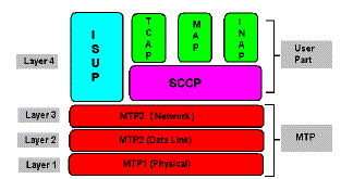
| As the call-flow examples show, the SS7 network is an interconnected set of network elements that is used to exchange message in support of telecommunications functions. The SS7 protocol is designed to both facilitate these functions and to maintain the network over which they are provided, like most modern protocols, the SS7 is layered. |
Physical Layer
|
| This defines the physical and electrical characteristics of the signalling links utilize DS-0 channels and carry raw signalling data at a rate of 56kbps or 64kbps (56kbps is the more common implementation). |
Message Transfer Part-Level2
|
| The level 2 portion of the message transfer part (MTP Level 2) provides link layer functionality. It ensures that the two end points of a signalling link can reliably exchange signalling messages. It incorporates such capabilities as error checking, flow control and sequence checking. |
Message Transfer Part-Level 3
|
| The level 3 portion of the message transfer part (MTP Level 3)extends the functionality provided by MTP level 2 to provide network layer functionality. It ensures that messages can be delivered between signalling points across the SS7 network. Regardless of whether they are directly connected. It includes such capabilities as node addressing, routing, alternate routing, and congestion control. Collectively, MTP levels 2 and 3 are referred to as the message transfer part (MTP). |
Signalling Connection Control Part
|
| The signalling connection control part (SCCP) provides two major functions that are lacking in the MTP. The first of these is the capability to address applications within a signalling point. The MTP can only receive and deliver messages from a node as a whole: it does not deal with software applications within a node. While MTP networkmanagement messages and basic call-setup messages are addressed to a node as a whole, other messages are used by separate applications within a node. Example of subsystem are 800 call processing, calling-card processing, advanced intelligent network(AIN),and custom local area signalling service(CLASS) services(e.g., repeat dialling and call return).The SCCP allows these subsystems to be addressed explicitly. |
Global Title Translation
|
| The second function provided by the SCCP is the ability to perform incremental routing using acceptability called Global Title Translation (GTT). GTT frees originating signalling points from the burden of having to know every potential destination to which they might have to route a message. A switch can originate a query, for examples, and address it to an STP along with a request for GTT. The receiving STP can then examine a portion of the message, make a determination as to where the message should be routed, and then route it. |
ISDN User Part (ISUP)
|
| The ISUP user part defines the messages and protocols used in the establishment and tear down of voice and data calls over the public switched network (PSN), and to manage the trunk network on which they rely. Despite its name, ISUP is used for both ISDN and non ISDN calls. In the North America version of SS7, ISUP messages rely exclusively on MTP to transport messages between concerned nodes. |
Transaction Capabilities Application Part
|
| TCAP defines the messages and protocol used to communicate between applications (deployed as subsystems) in nodes. It is used for database services such as calling card, 800 and AIN as well as switch-to-switch services including repeat dialling and call return. Because TCAP messages must be delivered to individual applications within the nodes they address, they use the SCCP for transport. |
Operations, Maintenance and Administration Part (Omap)
|
| OMAP defines messages and protocol designed to assist administrators of the SS7 network. To date, the most fully developed of these capabilities are procedures for validating network routing tables and for diagnosing link troubles. OMAP includes messages that use both the MTP and SCCP for routing. |
CALL DETAIL RECORDS
|
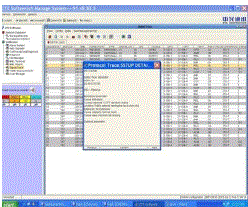
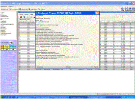
| The following figure describes the whole process to obtain the results. Every time there is a call attempt in the system a ticket or trace is created. It is necessary to wait until the call be terminated. Termination can be a normal clearing or due to some errors. For instance when “A” calls “B” then control information in full duplex channel flow via separate channel in SS&signalling or out band signalling. If it is voice over IP then control information flows via same channel along with the voice information. In ISUP control messages have basically six messages which flows between the two service points (SSP). They are as follows |
Initial Address Message (IAM)
|
| An initial address message (IAM) is sent in the “forward” direction by each switch needed to complete the circuit between the calling party and called party until the circuit connects to the destination switch. An IAM contains the called party number in the mandatory variable part and may contain the calling party name and number in the optional part. |
Address CompleteMessage (ACM)
|
| An address complete message (ACM) is sent in the “backward” direction to indicate that the remote end of a trunk circuit has been reserved. The originating switch responds to an ACM message by connecting the calling party’s line to the trunk to complete the voice circuit from the calling party to the called party. The terminating switch sends a ringing tone to the calling party’s line. |
Answer Message (ANM)
|
| An answer message (ANM) is sent in the “backward” direction, which indicates the beginning of a call i.e. the conversation starts here. It contains information such as billing, called party status so on. |
Call Progress (CPG)
|
| CPG is sent in either direction during the set-up or active phase of the call, indicating that an event, which is of significance, and should be relayed to the originating or terminating access, has occurred. |
Release Message (REL)
|
| A release message (REL) is sent in either direction indicating that the circuit is being released due to the cause indicator specified. An REL is sent when either the calling or called party “hangs up” the call ( cause=16). An REL is also sent in the backward direction if the called party line is busy (cause=17). |
Release Complete Message (RLC)
|
| A release complete message (RLC) is sent in the opposite direction of the REL to acknowledge the release of the remote end of a trunk circuit and end the billing cycle as appropriate. |
LITERATURE REVIEW
|
| “Analysis of Software Testing Strategies Through Attained Failure Size”,Zachariah,b. chh.shahu inst. Of bus.educ.&Res., Kolhapur,India |
| This paper discusses efficacy issues in software testing strategies through attained failure size. Failure size is the probability of finding an input that causes a failure in the input domain. As testing progresses, failure size decreases due to debugging. The failure size at the termination of testing is called the attained failure size. Using this measure, we compare the efficacies of partition testing and random testing, derive conditions that lead to the superiority of partition testing, and obtain optimal time allocations in partition testing. The core findings are presented in a decision tree to assist testers in test management. |
PROPOSED SYSTEM
|
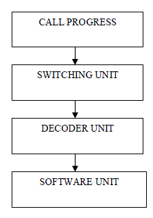
| In this project we develop the program for trouble shooting the call failures on ILD/NLD network. In our proposed system consist of four stages |
| 1. Call progress |
| 2. Switching unit |
| 3. C7 decoder unit |
| 4. Software unit |
CALL PROGRESS
|
| Initially when a call request is sent by a device and the switch, IAM message initialized by the switch connected to the calling party, (say A) to the switch connected to the called party, (say B). Following the request B acknowledges the request by sending ACM signal along with the ANM message to indicate that a certain amount of bandwidth is allotted for those device pair and is ready to communicate. |
| Later the conversation starts, the information signals are exchanged randomly and acknowledged, till any one subscriber sends a RLE message. This is a request and indication for the communication network to terminate the services provided to the subscribers. Hence when the request is acknowledged by the other switch, the call is terminated and the corresponding signal is send to the subscriber. |
SWITCHING UNIT
|
| In telephone network switching unit is very important because call progress is monitoring by switching unit. And then the switching units performs the following functions setup and release the end to end connections, handle mobility, handover requirements during the call, take care of charging, real time prepaid amount monitoring. |
| The main function of the switch is call routing and monitoring the call establishment. In telecommunication the following type of switch is used, such as Alcatel E10, Ericson AXE 810, and ZTE switch. This switching unit monitoring the call progress after terminating the call, information about the call converted into raw data. |
DECODER UNIT
|
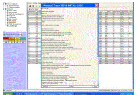
| In decoding unit c7 decoder software is used. C7 decoder is a network protocol analyser and it is easy to use. It is used to convert the switching unit raw data information into text format. |
PROGRAM/SOFTWARE
|
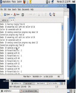
| Network simulator2 software is used to analyse the call failure. The decoding unit output is given to program input. NS2 software analyses the decoding output and separates the successful call and failed call. |
TRACKING OF REQUIRED PARAMETERS
|
| It is possible to make a detailed analysis from some of the parameters that are follows |
Initial Address Message
|
| Provides the status of the Echo Control Device Indicator Field. |
Transmission Medium Requirement
|
| Provides the value of the Traffic-restart-allowed message inKHZ |
Called Party
|
| To obtain the value for the Internal Network NumberIndicator,Address Signal? fields. |
Calling Party
|
| To obtain the values for the Calling party Category, Calling party number Incomplete Indicator andAddress signal? fields. |
Address Complete Message
|
| To get the status of the Charge Indicator and Address Signalfields. |
Call Progress
|
| To obtain the status of the charge Indicator? and Echo Control Devices Indicator? values. |
Release
|
| To obtain the Cause Value? of the call termination. For a failed calls the RLE parameter can be obtained can be of the form: |
| (R)==>REL: Time = 07:11:31:6 |
CONCLUSION
|
| In this paper NS2 software is used to analyse the call failure. From that telecommunication unit take the necessary recovery method to improve their network. For that their network efficiency ratio increased and revenue loss decreased. Now they analyse the call failure manually, which is time consuming. NS2 software will use, decrease the man power usage and reduce the time. In future other than NS2 programs are easy to analyse the call failure in telecommunication network. |
Figures at a glance
|
 |
 |
 |
 |
| Figure 1 |
Figure 2 |
Figure 3 |
Figure 4 |
 |
 |
 |
| Figure 5 |
Figure 6 |
Figure 7 |
|
| |
References
|
- A new SS7-SIGTRAN protocol interchanger softwareoperated with modified USB E1 for nationwide IP backbone -Necessity for BTCL
- Signaling system 7 (SS7) network security Moore, T. ;Kosloff, T. ; Keller, J. ; Manes, G. ; Shenoi, Sujeet Circuitsand Systems, 2002.
- Safe and effective error rate monitors for SS7 signalinglinks Schmidt, Douglas C.Selected Areas in Communications, IEEE Journal on
- MEMS single-chip5×5 and 20×20 double-switch arraysfor telecommunication networks Braun, Stefan ; Oberhammer,Joachim ; Stemme,
- Analysis and Implementation of a Power Switch forTelecommunication Applications Pahlevaninezhad, Majid ;Khajehoddin, S. Ali ;
- Analysis of Software Testing Strategies Through AttainedFailure Size by Zachariah, BabuChh. Shahu Inst. of Bus. Educ. & Res.,
- Evaluation of Call Dropping Probability for aHeterogeneous Wireless Network with Uniformly DistributedHandoff Failure Rates Aalo,
- Optimum design of Viterbi decoder for high speed datatelecommunication receivers with 802.16a case studyRohani,Ehsan Dept. of
- American national standard for telecommunications - Signaling system number 7: Integrated services digital network (ISDN) user
- American national standard for telecommunications - Signaling system number 7: Message transfer part (MTP), 1992
- American national standard for telecommunications - Signaling system number 7: Signaling connection control part (SCCP), 1992
- American national standard for telecommunications - Signaling system number 7: Transaction capabilities application part (TCAP), 1992
- Bellcore Bell Communications Research specification of signaling system number 7, 1991
- Common channel signaling network interface specification supporting network interconnection, message transfer part, and integrated
- Compatibility information for interconnection of a wireless services provider and a local exchange carrier network, 1993
|