ISSN ONLINE(2278-8875) PRINT (2320-3765)
ISSN ONLINE(2278-8875) PRINT (2320-3765)
Mrs.R.Vidhya1, R.Rohini Priya2
|
| Related article at Pubmed, Scholar Google |
Visit for more related articles at International Journal of Advanced Research in Electrical, Electronics and Instrumentation Engineering
The proposed work is to design an intelligent control system based on Neuro-Fuzzy technique (ANFIS) where, a model of a vision platform for any kind of aerial vehicle is considered. The aerial vehicle’s motion is sensed with the help of an accelerometer sensor which is monitored using a Graphical Programming Language –Lab VIEW. An intelligent control approach has been utilized whose output controls the vision system – the camera of the aerial vehicle, through a servo signal. The accelerometer readings from the real world are communicated to the monitoring system using MyDAQ equipment, which is used for Data Acquisition .The image acquisition module and the ANFIS control strategy to control the camera have been produced.
Keywords |
| Aerial vehicle, Motion & tilt Sensing, MyDAQ, Neuro-Fuzzy approach |
INTRODUCTION |
| Aerial vehicles are subjected to highly dynamic vibrations from several sources such as the vibrations produced from engine, rotor blades, are especially high during landing and takeoff. These vibrations cause considerable loss in the quality of the captured images being displayed for the pilot’s view. In the present system, post filtering is used which can introduce a significant phase lag, reducing undesirably the control bandwidth of the helicopter. |
| As vibration isolation problems in small size aircrafts are more difficult and the possible options to diminish them are limited to requirements of low weight and low power consumption which results in increased cost of the vision system . |
| In this project, vision system will be using optimal quality cameras to perform the image capture. In addition to the reduction of the vibrations influenced over the captured images [3], the motion of the dynamic platform holding the cameras should have a soft, accurate and rapid response. |
| The work presents an intelligent control strategy – ANFIS(Adaptive Neuro-Fuzzy Inference System) in order to improve the whole performance of an aerial vehicle’s vision system. The existing system has vision control strategy that works on Neural Networks approach which is found to be devoid of logical thinking and decision making ability those of which could be admired along with human comprehensibility in Fuzzy Logic systems. |
| Neuro Fuzzy technique based on a given set of input-output data sets is being trained with the sequence of input and output functions helps to solve this disadvantage. The purpose of using LabVIEW is the ease of implementation of data acquisition from sensor as well as the advantage of instrumentation control of the image capture platform. |
| The proposed work can be divided into three modules: |
| Module I-Data Acquisition from the Accelerometer sensor |
| Module II-The ANFIS Control Strategy [2] |
| Module III-Vision Acquisition |
| In module I, Data Acquisition from the accelerometer sensor and the simulation environment developed is presented. |
| In module II, The ANFIS Control Strategy is depicted. In fact, an Adaptive Neuro -Fuzzy Inference System can be used to devise the development of this Intelligent Control Strategy [5]. In module III, The Vision Acquisition program has been developed and the resultant image capture from the Aerial Vehicle’s Vision System could be viewed [6]. |
<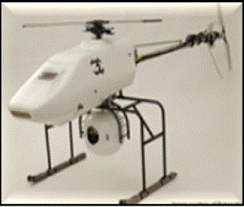 |
| Figure 1: Prototype of aerial vehicle with a vision system attached below it. |
II.SYSTEM DESIGN |
| The accelerometer sensor, ADXL335 is a complete 3-axis acceleration measurement system, having a measurement range of ±3 g minimum. It operates as a polysilicon surface-micro machined sensor and signal conditioning circuitry to implement an open -loop acceleration measurement architecture. The output signals are analog voltages that are proportional to acceleration [3]. The accelerometer can measure the static acceleration due to gravity in tilt-sensing applications as well as dynamic acceleration resulting from motion, shock, or vibration. |
| This output being an analog voltage signal cannot be connected directly to any system .Hence we use the interfacing equipment called My DAQ. The My DAQ is a data acquisition system, a collection of software and hardware that lets you measure or control physical characteristics in the real world. A complete data acquisition system consists of data acquisition (DAQ) hardware, sensors and actuators, signal conditioning hardware and a computer running data acquisition (DAQ) software. |
| Here we have the My DAQ to be interfaced between the accelerometer sensor and the computer running data acquisition (DAQ) software which is the PC supporting LabVIEW. The PC with LabVIEW has been installed with the components of latest version LabVIEW 12.0 containing the driver software for supporting the angle measurement and monitoring system and the vision acquisition and display module. Further, the control strategy module [2] which controls the positioning of the camera is being programmed in this PC which produces an output based on the acquired angle of motion of the plane and this changes the camera position. A servomotor assembly [3] consisting of the servomotor and the camera needs to be set-up which performs the following. |
| A servomotor has to be set up such that it interfaces with the PC supporting LabVIEW in order to receive the inputs from the PC to perform tilting of the position of the camera. Thus the camera needs to be fixed above this servomotor assembly [1] which acquires the aerial view of the vehicle in motion and sends it to the PC for displaying it to the pilot. The servomotor moves the camera’s position accordingly based on the output from PC which decides the camera position by applying the ANFIS control strategy developed. |
<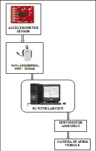 |
| Figure 2.Flow diagram of System design |
| The Figure 2 shows the concept of acquiring the angle of motion from the vehicle in motion and thus achieving the goal of changing the position of the camera of vision system according to the angle received that is being measured from the aerial vehicle. |
| Thus the aim of controlling the camera position to avoid blurring of captured images [6] during the motion of the aerial vehicle due to oscillatory motion of the vehicle with the ANFIS control strategy [5] is being shown in the above flow of the work. Now the modules used in the system shall be explained in detail. |
III. DATA ACQUISITION FROM ACCELEROMETER |
| The ADXL335 being used here as the acceleration sensor which is a complete 3-axis acceleration measurement system, having the output signals as analog voltages that are proportional to acceleration given as input signal to the MyDAQ equipment. The accelerometer can measure the static acceleration due to gravity in tilt-sensing motion of the aerial vehicle as well as dynamic acceleration resulting from vibrations that degrade the image capture in vision system. |
| The MyDAQ is a low-cost portable data acquisition (DAQ) device which uses LabVIEW-based software instruments, allowing to measure and analyze real-time signals. We use this since it is ideal for exploring and taking sensor measurements. When combined with LabVIEW on the PC, we can analyze and process acquired signals and control processes that are required for data acquisition techniques |
| There are two analog input channels on NI Mydaq, where a single ADC converter is used to sample both channels, which can measure up to ±10 V signals |
<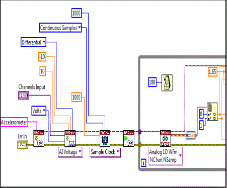 |
| Figure 3: Block diagram showing the interfacing of sensor with MyDAQ for reading values in degree to produce analog voltage values |
| The following section will describe the icons used in this module to interface the accelerometer and PC powered with LabVIEW and also the conversions involved ; |
| DAQ mx Create Task; Creates a task and adds virtual channels to that task if you specify them in the global virtual channels input. |
| DAQmx Create Virtual Channel (VI); Creates a channel or a set of virtual channels and adds them to a task. |
| DAQmx Timing (VI)- Sample Clock;Configures the number of samples to acquire or generate and creates a buffer |
| when needed. The instances of this polymorphic VI correspond to the type of timing to use for the task. |
| DAQmx Start Task (VI); Transitions the task to the running state to begin the measurement or generation. |
| DAQmx Read (VI); Reads samples from the task or virtual channels you specify that is samples to return, whether to read a single sample or multiple samples at once or from one or multiple channels. |
| Function to Wait Until Next ms Multiple ; Waits until the value becomes a multiple of the specified millisecond multiple to control loop. |
| DAQmx Stop Task(VI); Stops the task and returns it to the state the task was in before. |
| DAQmx Clear Task (VI); Clears the task and releases any resources the task reserved. You cannot use a task after you clear it unless you recreate the task |
| Error in/out;it contains error information and indicates if error occurs in any VI |
| Accelerometer in Degree;it displays the analog voltage value which has been converted to degrees |
| This module works as follows, the accelerometer sensor produces values of angles, where this it is being interfaced with the My-DAQ equipment as shown in the above Figure 3 which converts this analog voltage signal to digital signal. This output is being given to the PC with LABVIEW. This module performs the operation of converting the angular signals measured due to motion of the aerial vehicle into analog voltage values. |
IV. CONTROL STRATEGY BASED ON ANFIS |
| In this work, it is such that the camera should be kept without considerable movement when the images are being captured. The control system performance depends on the angle and the vibration characteristics affecting the camera position based on the pitch angle error and the yaw angle error. The control strategy could be calculated for each combination of pitch angle and yaw angle. |
| In this way, a combination of nearly 1000 different inputs could be obtained. In this process, yaw values from -90º to 90º, pitch values from -90º to 90º, have been considered as suggested in [2]. |
<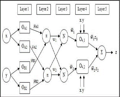 |
| Figure 4: ANFIS architecture |
| The Neural Networks at present have learning properties that are adequate for the problem undertaken but is said to suffer from poor logical decision making. Hence an alternative Neuro-Fuzzy approach proposed by Jang [3] been used. This kind of approach is known as Adaptive Neuro-Fuzzy Inference Systems (ANFIS systems) , where a neuroadaptive learning method has been used. This method works similarly to neural networks, using a given input/output data set, based on a set of rules and assigns values to the output module.The training involves the choice of the membership functions, fuzzy logics operators, the design of fuzzy rules, the choice of the aggregation mechanism, the inference from the fuzzy rules and the defuzzification method for obtaining a numeric output. |
| The three main phases of ANFIS: |
| 1)collection of input/output data in a form that it will be usable by ANFIS for training; |
| 2)the creation of a Fuzzy System as initial structure, and |
| 3)the application of a learning algorithm consisting of a combination of the least-squares method and the back propagation gradient descent method for training the ANFIS parameters. |
| In this paper, the input to the ANFIS system are the pitch angle, the yaw angle, the frequency of the vibration in the gravity axis and the frequency of the vibration in the perpendicular axis, whereas the outputs are the proportional constants for servomotor to adjust camera positions. The ANFIS should be trained with the data obtained above and then validated ANFIS system is to be tested using real –world interfacing, whose outputs control the servomotor. |
<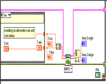 |
| Figure 5: ANFIS based control strategy |
| This module describes how the position of the camera is varied with reference to the accelerometer sensor’s input. The angle of the vehicle is being measured which is the input used to tilt the camera based on this angle measured from the accelerometer sensor. |
V. VISION ACQUISITION MODULE |
| Once the intelligent control strategy depicted in the previous section, produces its output it controls the vision acquisition platform, along with the simulation results of the trials are shown in this section. Several trials have been carried out. In these trials as it was pointed out in the previous section desired yaw values from -90º to 90º and pitch values from -90º to 90º have been considered. |
| This functionality opens up a number of possibilities for the augmentation of collected data by images. For example, webcam images can be embedded in front panels for monitoring remote hardware or even for remote experimentation. As another example, webcam images can be processed for information that can then act as a trigger for other data collection operations. Each servomotor is a motor with a tilting functionality of 1800. Hence we use two different servos one for the vertical direction to rotate the camera for Yaw angle adjustment and the second one for the horizontal direction to rotate the camera for Pitch angle adjustment. These functions are being calibrated by the ANFIS control strategy with the provided training set of vector functions. |
| Thus the vision system acquires images to be displayed in the pilot’s cockpit for clear viewing which is depicted below. |
<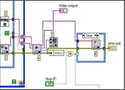 |
| Figure 6: Block diagram for vision acquisition module |
| The following section will describe the icons used in this module to interface the accelerometer and PC powered with LabVIEW : |
| IMAQdx Open Camera VI Opens a camera, queries the camera for its capabilities, loads a camera configuration file, and creates a unique reference to the camera |
| IMAQdx Read Attributes VI Loads a configuration file for a camera |
| IMAQdx Configure Grab VI Configures and starts a grab acquisition that loops continually, for high-speed image acquisition |
| IMAQdx Grab VI Acquires the most current frame into Image Out. If the image type does not match the video format of the camera it changes that to a suitable format. |
| Vision acqusiition to calculate FPS Calculates frames per second within the loop |
| IMAQdx Close Camera VI Stops an acquisition in progress, releases resources associated with an acquisition, and closes the specified Camera Session |
| IMAQ Create VI Creates a temporary memory location for an image. Use IMAQ Create in conjunction with the IMAQ Dispose VI to create or dispose of NI Vision images in LabVIEW. |
| Error in/Error out this function is used to accept errors and reduces their effects. |
| This module working could be given as follows : |
| The accelerometer sensor produces values of angles which is an analog voltage signal. The accelerometer sensor is being interfaced with the My-DAQ equipment as shown in the Figure 2 which converts this analog voltage signal to digital signal. This output is being given to the PC with LABVIEW. This module performs the operation of converting the Voltage Signal into angular values. |
VI. SIMULATED OUTPUTS |
<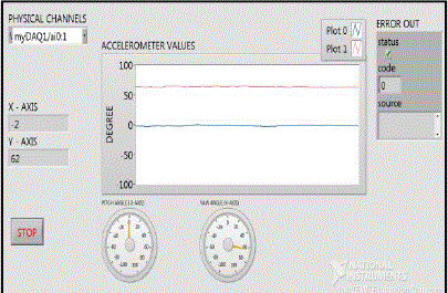 |
| Figure 7: Readings of Yaw angle from accelerometer |
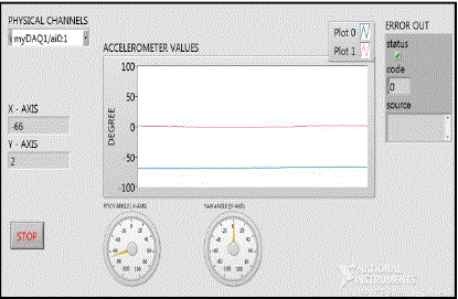 |
| Figure 8: Readings of Pitch angle from accelerometer |
| The above Figure 7 & 8 shows the output for readings acquired from the accelerometer sensor described as follows: As physical channels channel 0 & channel 1 of the MyDAQ equipment are to be connected, the display of connected channels are shown by the physical channels function. The accelerometer senses values converted to degree and being displayed as in the two directions of X and Y axes. An error which has been sensed while measuring the angles by accelerometer gets displayed by the error out function. |
| A SIMPLE CONTROL STRATEGY USING LabVIEW |
<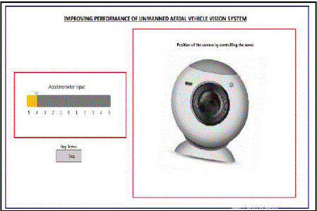 |
| Figure 9: Position of camera when tilted right |
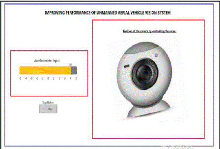 |
| Figure 10: Position of camera when tilted left |
| The above Figure 9 and 10 shows the a simple control strategy [2] for controlling the position of the camera when aerial vehicle is moving right and left . |
| The concept lies in tilting the camera in the opposite direction to the angle being measured, For instance, |
| 1) vehicle tilted towards left camera moves right |
| 2) vehicle tilted towards right camera moves left |
| VISION ACQUISITION OUTPUT |
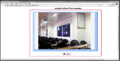 |
| Figure 11: Image captured from camera using vision acquisition module |
| The above Figure 11 shows us the vision acquisition module of how images are being captured . Here the camera is to be kept at the vehicle’s front nozal tip and it begins to view and capture images from the aerial vehicle [6] at the rate of 30 frames per second, which is displayed to the driver. Thus acquiring an unblurred image through this vision acquisition module has been depicted above. |
VII. CONCLUSION |
| In this work two different acquisition techniques have been utilized. Data based acquisition using the accelerometer sensor detects the angle of vehicle’s motion which can be converted to degrees using the PC with LabVIEW when interfaced with the My DAQ equipment. Vision based acquisition captures the aerial view from the aerial vehicle and displays this to the pilot. The Control strategy provides systematic control of the camera’s position to avoid blurred images. In the future enhancement these recognition techniques can be used in any type of vehicle’s application. Neuro-Fuzzy algorithm enhances human comprehensibility of such vision applications where if-then rules are implemented which controls the servomotor of the camera by providing a servo signal in the control strategy program. intelligent control strategy based on ANFIS systems has been devised and tested. Satisfactory results have been achieved in the carried out trials. |
References |
|