Keywords
|
| Artificial Neural Networks, Distance protection, FACTS devices, Thyristor Controlled Series Capacitor, |
INTRODUCTION
|
| Presently due to the deregulation of power industry and the restriction faced by power industry due to energy, environmental and regulatory issues, the main challenge is to improve the power transfer capability and also to improve the system integrity of the given transmission facility. The above mentioned problem can be addressed by using series compensation. Series compensation when introduced in power systems influences the power flow in a particular network segment which reduces active power losses and also prevents system - sub synchronous oscillations[1]-[3]. |
| FACTS device are normally used in power systems which takes care of the power transfer capability, voltage stability and power oscillation damping. Thyristor Controlled Series Capacitor (TCSC) is one of the series compensation device used but, the use of TCSC creates certain problems for conventional distance protection schemes due to the changes in the apparent impedance measured by the relay. The apparent impedance seen by the relay is influenced by the uncertain variation of series compensation voltage [4]-[5]. |
| Providers of transmission facilities normally prefer distance protection as the primary protection system, As series compensation is introduced in power transmission lines it needs additional attention while choosing the protection scheme as series compensation requires extra care in addition to the well know protection challenges on HV transmission networks . In modern days power system protection systems has become intelligent has it uses micro processor based techniques like Artificial Neural Networks to improve distance protection of transmission line with TCSC compensation which uses back propagation algorithm and is extensively tested using MATLAB Simulation for different conditions[6]-[11]. |
| This paper is organized as follows: In the first section the introduction to Protection of Series Compensated Transmission Lines using Artificial Neural Networks is discussed, in the second section brief introduction of Thyristor Controlled Series Capacitor(TCSC) is presented, in the third section Artificial Neural Networks are discussed, in the fourth section Distance Protection basics and effect of SC Compensation on Protection is presented, in fifth section simulation methods used and results are presented and in sixth section conclusions based on the results obtained are presented. |
THYRISTOR CONTROLLED SERIES CAPACITOR
|
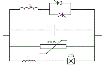
| For many years series compensation technique is used to adjust the power transfer between two stations by adjusting the net series impedance of the line. Installation of a series capacitor is a conventional and established method of increasing transmission line capacity, by reducing the net series impedance, thus increasing power transmission. As this method is well established method but, due to the limitation of its slow switching time it is replaced by Thyristor controllers, which are fast acting devices due to which rapid and continuous control of line compensation is possible. Thyristor Controlled Series Capacitor (TCSC) is one of the controllers used for series compensation. TCSC is a FACT device which is a combination of thyristor-controlled reactor (TCR) parallel with capacitor. TCR is a variable inductive reactor XL (α) controlled by firing angle α. The variation of XL (α) with respect to α can be calculated by [12]: |
 |
| The controlled reactor is placed across the series capacitor, so that TCSC can be modelled as a variable parallel LC circuit, made of a fixed capacitive impedance Xc, and a variable inductive impedance XL (α), as follows, |
 |
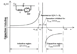
| where α is the delay angle measured from the peak of the capacitor voltage (or, equivalently, the zero-crossing of the line current). For α between 0 to 90, XL (α) is varied from minimum value ( =ωL) to its maximum (infinity), hence effective reactance of TCSC starts increasing from its minimum value of (XLXc/(XL.Xc)) at α=0, to till occurrence of parallel resonance condition at Xc = XL (α), theoretically XTCSC is infinite which is known as inductive region. Still increasing of XL (α) gives capacitive region, here TCSC reactance XTcsc (α) starts decreasing from infinity point to minimum value of capacitive reactance XC= l/ωC. Fig. 2 shows the impedance characteristic curve of TCSC versus the firing angle α. From figure we see that both capacitive and inductive regions are possible by varying firing angle (α). |
| In practical scheme, the TCSC is usually made with a Metal Oxide Varistor (MOV) and a bypass switch used as protective devices, as per Fig. 1 MOV, which is a nonlinear resistor, protects the TCSC against high capacitor overvoltage by providing a alternate path for the fault current. The V-I characteristic of MOV is calculated by the following exponential equation: |
 |
| where IMOV and VMOV are MOV current and voltage; IRef and VRef are the reference quantities and q is an exponent of the characteristic. A circuit breaker is also present across the TCSC to bypass it if a severe fault or equipment malfunction occurs. There is also provision for a current limiting inductor, Ld, in the circuit breaker branch to restrict the capacitor current during the bypass operation |
| A. Different Modes Of Operation |
| By changing the firing angle of the thyristors the effective reactance of the TCR is varied. This variable TCR reactance in parallel with a fixed capacitor combination makes the TCSC to operate in four different modes; blocking mode; bypass mode; capacitive boost mode; and inductive boost mode. Since we are interested in the problem faced by the protection scheme in this paper we only take up the capacitive boost mode which is used for increasing the power transfer capability of the particular line segment. |
| B. Capacitive Boost Mode |
| In capacitive boost mode of operation a trigger pulse is supplied to the thyristor having forward voltage just before the capacitor voltage crosses the zero line, so a capacitor discharge current pulse will circulate through the parallel inductive branch. The discharge current pulse adds to the line current through the capacitor and causes a capacitor voltage that adds to the voltage caused by the line current. The capacitor peak voltage thus will be increased in proportion to the charge that passes through the thyristor branch. The fundamental voltage also increases almost proportionally to the charge. From the system point of view, this mode inserts capacitors to the line up to nearly three times the fixed capacitor. This is the normal operating mode of TCSC. |
ARITIFICAL NEURAL NETWORKS
|
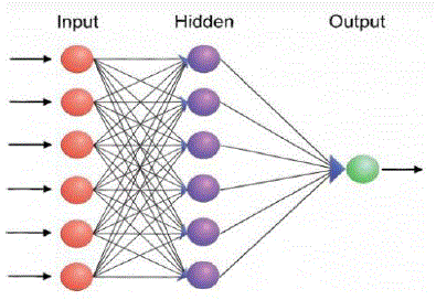
| An Artificial Neural Network, just named as Neural Network, is a mathematical model inspired by biological neural networks. A neural network consists of an interconnected group of artificial neurons, and it processes information using a connectionist approach to computation. In most cases a neural network is an adaptive system changing its structure during a learning phase. Neural networks are used for modelling complex relationships between inputs and outputs or to find patterns in data. There are |
| ? Modelling |
| ? Forecasting and prediction |
| ? Estimation and Control |
| To train an ANN using BP to solve a specific problem there are generally four major steps in the training process: |
| ? Step 1- Assemble the suitable training data |
| ? Step 2- Create the network object |
| ? Step 3- Train the network and |
| ? Step 4- Simulate the network response to new inputs. |
DISTANCE PROTECTION BASICS AND EFFECTS OF SC ON PROTECTION
|
A. DISTANCE RELAYS
|
| Distance relays, as the name says, measures distance. This is true in case of transmission line, as distance relay measures the impedance between the relay point and the fault location. This impedance is proportional to the length of the conductor, and hence to the distance between the relaying point and the fault [13]. |
B. Zones Of Protection
|
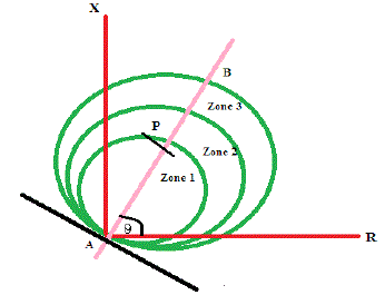
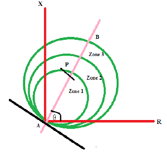
| Basically distance protection has instant directional Zone 1 protection and one or more time delayed zones. Numerical distance relays consists up to five zones, of which some are used in the reverse direction. The instant Zone I protection setting is up to 85% of the protected line using Numerical distance relays. The Zone 2 protection setting should be at least 120% of the protected line impedance. Zone 3 reach should be set to at least 1.2 times the impedance presented to the relay for a fault at the remote end of the second line section [13]. Typical reach for a 3-zone distance protection are shown in Fig.4. |
| where AB Protected line θ Line angle AP Impedance setting |
C. Effect Of Tcsc On Distance Protection
|
| Series compensation using TCSC plays a crucial role in loaded transmission lines. The usage of TCSC in transmission networks requires additional studies into the expected performance of the new system and also the influence on the operation of existing protection control and monitoring systems. Due to the introduction of series capacitance in the line, the line reactance creates problems for the effective operation of impedance based distance relays. The relays, which make use of impedance measurements in order to determine the presence and location of faults, are "fooled" by installed series capacitance on the line when the presence or absence of the capacitor in the fault circuit is not known priori. |
| TCSCs and their overvoltage protection devices (typically Metal Oxide Varistors (MOVs) and/or air gaps), in spite of their beneficial effects on the power system performance, introduce additional problems and make the operating conditions unfavourable for the protective relays that use conventional techniques and include phenomena such as voltage and/or current inversion, sub harmonic oscillations, and additional transients caused by the air gaps triggered by thermal protection of the MOVs. The apparent reactance and resistance seen by the relay are affected due to the variation of series compensation voltage during the fault period. |
D. Effect Of Tcsc On Zones Of Protection For A Distance Relay
|
| Due to the introduction of TCSC the apparent reactance and resistance seen by the relay are affected due to the variation of series compensation voltage during the fault period. Due to which the Conventional relay gets tripped unnecessarily even though the fault is not present in its zone of protection [3], [5]. |
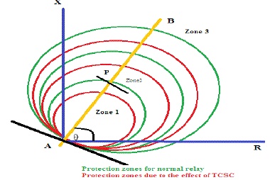
| Introduction of TCSC results in the changes of zones of protection of normally set distance relay used for transmission line protection. Fig.5 shows the zones of protection of a transmission line when TCSC is introduced, and Fig. 6 shows the combination of Fig. 4 and Fig. 5 to get a clear understanding of presence of TCSC |
| where AB Protected line θ Line angle AP Impedance setting |
SIMULATION AND RESULTS
|
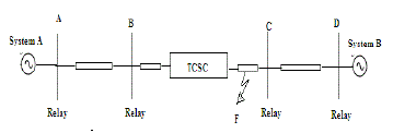
| The test system used for in this paper is a 500KV, 60 Hz power system which has two sources corresponding to two areas joined by a 400km transmission line. The system parameters used for simulation are given in table (1) in Appendix. In this system the TCSC is placed in the middle of the transmission line as per the single line diagram shown in fig. 7 |
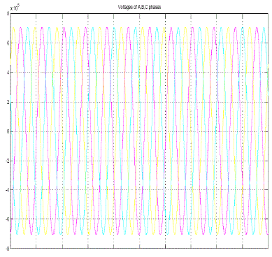
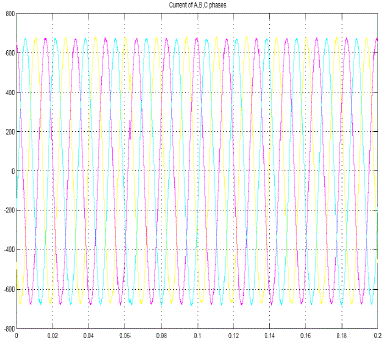
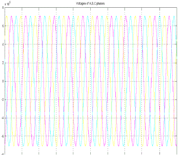
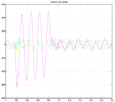
| The model shown in the single line diagram is modelled for computer simulation in MATLAB/Simulink environment. After the simulation waveforms for different operating conditions are taken Fig. 8 and Fig. 9 shows a three phase voltage and current waveforms without TCSC in the system. Fig.10 and Fig.11 shows the voltages and current waveforms with TCSC present in the system. Fig. 11 also shows that whenever a fault occurs on the system the fault current increases abruptly and comes to normal condition after fault is cleared. For different test conditions voltages and current values are collected from them, by the help of fast fourier analysis tool box present in the MATLAB tool box the voltages and currents at the relay are calculated. Based up on the values of voltages and currents at different test conditions and different fault conditions impedance of that particular line section is calculated and the results are presented in table (I). |
| Based on the results of table (I) the relay present for protection of that particular zone sends a wrong trip signal which is shown in table (II). As we already discussed in introduction that due to the introduction of TCSC there is a problem for protection circuit which has to be corrected, this change in impedance is corrected with the help of Artificial Neural Network. |
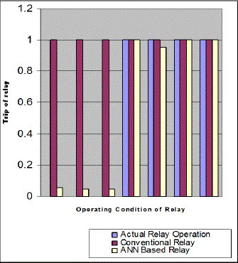
| The training cases used for the training of the ANN are generated using MATLAB/Simulink test system shown in fig. 7 for various kinds of faults (LLL-Fault, LL-Fault and LG-Fault) fault location (90%, 85%, 80%, 70%, 60% and 50% length of line) and with different firing angles of TCSC (60°, 63°, 65°, 68° and 70°), with all the above different training cases different training vectors were collected at a sampling rate of 16 samples/cycle. The inputs given for the training of ANN are voltage, current of the relay location and firing angle at which TCSC is operating. The output expected from the ANN system is trip or a no trip signal to the circuit breaker in the form of [0 0 0 1 1 1 1]. ANN uses back- propagation algorithm for its training purpose and the number of neurons in the hidden layer is decided based on the trial and error method. In the present problem based on the trial and error method we come to the conclusion that with 10 neurons in the hidden layer gives better results. The results for expected output and the output obtained after training are compared as shown in table (III). The results for expected output and the output obtained after training are compared with the help of bar graph for better understanding as shown in Fig. 12. |
CONCLUSION
|
| The introduction of TCSC has advantages like improvement in stability; enhanced active power transfer capability but it creates certain problems to conventional distance protection scheme when used by transmission lines as there is a change in the apparent impedance measured by the relay. The results obtained from simulation for different types of faults and different operating points (with firing angles α = 60° to 70°) of TCSC. They indicate that presences of TCSC when operating in capacitive mode have changed the impedance measured by the relays used by the protection system, which caused mal operations (like over reach) of protective relay. This mal operation is avoided by ANN trained by Back Propagation Algorithm. ANN based relay gives promising results (for tripping condition (0, 1)) compared to conventional relay with the presences of TCSC. The fault distance can also be obtained with the above network by selecting proper training pairs which will be presented in future work. |
ACKNOWLEDGMENT
|
| The main author would like to sincerely thank his supervisor Mr. V Surendranath Chowdary for his valuable guidance and advices. He would also like to express his truthful appreciations to faculty of Sreenidhi Institute of Science & Technology which supported me in this research paper. |
Tables at a glance
|
|
|
| |
Figures at a glance
|
 |
 |
 |
 |
| Figure 1 |
Figure 2 |
Figure 3 |
Figure 4 |
 |
 |
 |
 |
| Figure 5 |
Figure 6 |
Figure 7 |
Figure 8 |
 |
 |
 |
 |
| Figure 9 |
Figure 10 |
Figure 11 |
Figure 12 |
|
| |
References
|
- MojtabaKhederzadeh and T. S.Sidhu, “Impact of TCSC on the Protection of Transmission Lines”, IEEE Transactions on Power Delivery,Volume 21 January 2006, pp.80-87.
- SarathKapuduwage, “Fault Location on the High Voltage Series Compensated Power Transmission Networks”, Thesis, December 21,2006.
- S. G. Srivani and K. PandurangaVittal, “Integrated Adaptive Reach Setting of Distance Relaying Scheme in Series Compensated Lines”,International Journal on Electrical Engineering and Informatics - Volume 2, no. 4, 2010, pp.291-297.
- AlirezaSolat, and Ali Deihimi, “A Novel Scheme for Distance Protection of Series Compensated Transmission Lines with TCSC UsingArtificial Neural Netwoks”, 20th Iranian Conference on Electrical Engineering,(ICEE2012),May 15-17,2012.
- Zellagui Mohamed and ChaghiAbdelaziz, “Impact of Series Compensation Insertion in Double HV Transmission Line on the Settings ofDistance Protection”, International Journal of Scientific & Engineering Research Volume 2, Issue 8, August-2011, pp.1-7.
- Suhaas Bhargava Ayyagari, “Artificial Neural Network Based Fault Location for Transmission Lines”, Thesis, June 12, 2011.
- Sunita Tiwari and S.P. Shukla, “COMPENSATION BY TCSC IN OPEN LOOP CONTROL SYSTEM”, IJAET/Vol.III/ Issue I/January-March, 2012, pp.175-179.
- Upendar, C. P. Gupta, and G. K. Singh,“Comprehensive Adaptive Distance Relaying Scheme for Parallel Transmission Lines”Transactions on Power Delivery, Volume 26, no. 2, April 2011, pp.1039-1059.
- Dragan Jovcic and G. N. Pillai“Analytical Modelling of TCSC Dynamics” IEEE Transactions on Power Delivery, Volume 20, no. 2,April 2005, pp.1097-1104.
- A.H. Osman, Tamer Abdelazim and O.P. Malik, “Transmission Line Distance Relaying Using On-Line Trained Neural Networks”,Transactions on Power Delivery, Volume 20, no. 2, April 2005, pp.1257-1264.
- Clint T. Summers, “Distance Protection Aspects of Transmission Lines Equipped with Series Compensation Capacitors”, ThesisSeptember 29, 1999.
- Hingorani NG, Gyugyi L. Understanding FACTS: concepts and technology of flexible AC transmission systems, New York: IEEEPress; 1999.
- B. Ram & D.N. Vishwakarma, “Power system protection and switchgear”, Tata McGraw– Hill Publishing Company Limited, New Delhi1995.
- Sivanandam, S.N. Deepa, “Introduction to Neural Networks using MATLAB 6.0”, Tata McGraw– Hill Publishing Company Limited,New Delhi 2006.
|