International Journal of Advanced Research in Electrical, Electronics and Instrumentation Engineering
ISSN ONLINE(2278-8875) PRINT (2320-3765)
ISSN ONLINE(2278-8875) PRINT (2320-3765)
| Harsh Kapadia1, Alpesh Patel2 Assistant Professor, Dept. of Electrical Engg., Institute of Technology, Nirma University, Ahmedabad, Gujarat, India 1 |
| Related article at Pubmed, Scholar Google |
Visit for more related articles at International Journal of Advanced Research in Electrical, Electronics and Instrumentation Engineering
This paper predominantly emphases on two algorithms Hough Transform and the Sub-Pixel Edge Detection and their application on 1-Dimensional barcode scanning. The system is meant to verify Barcode on-line. It primarily focuses on two aspects of barcode verification. One is two detect the angle if barcode is skewed in the image and correct the same. The other is to detect the edges of a barcode in real time blurred image using sub-pixel edge detection. First of all we have explained the basic theory of 1-D barcode that was used i.e. EAN-13. Then the Hough Transform and Sub-Pixel Edge Detection are explained in detail. After that I have explained the need of both the algorithm in barcode verification. The paper also embraces MATLAB implementation steps of the system including both this algorithms with results.
Keywords |
||||||||||||||||||||||||||||||||||||
| EAN-13, Hough Transform, Sub-pixel edge detection, Interpolation | ||||||||||||||||||||||||||||||||||||
INTRODUCTION |
||||||||||||||||||||||||||||||||||||
| Nowadays immense advancement has been done in the branch of Image Processing and Computer Vision. Image Processing involves changing the nature of an image in order to either improve its pictorial information for human interpretation, or render it more suitable for autonomous machine perception. It is a branch of science which deals with image intensity values. Its applications focus on intelligent machines and systems which includes Barcode verification and recognition, Traffic control system, Security systems, Fault and Auto-rejection system etc. Here we have worked to develop a system to recognize EAN-13 barcode online. EAN-13 is mostly common in retail items. Online word here means at the time of production in the industry. Most of the industries producing retails products will contain barcode generator software which generates EAN-13 barcode particular for that industry and that product. Here to verify whether the barcode generated by the software and the barcode printed are matching or not is very much important. If not verified it can create trouble in scanning at the point of sale. This point defines the problem on which our work is based. | ||||||||||||||||||||||||||||||||||||
| Barcodes are introduced in 1960s.It is the most popular automatic identification technology used in many applications. A barcode is a machine readable code of a series of bars and spaces printed in defined ratios, whose principle function is to convey data. Simply barcodes are formed of parallel lines which may be thick or thin depending on the data encoded in the code. Their first application was in rail road cars. The invention of barcode was a result of developing an application for identifying products of all kinds, especially in super markets. Today barcodes are almost everywhere. They are more popular in consumer products. They help automate the process of production and reduce human error. Automatic Identification eliminates two error prone and time consuming activities – manual data collection and data entry. Barcodes find important applications in computer technology, especially in the area of manufacturing, distribution, selling, as well as in the development of management information. There are almost dozens of Barcodes currently in use such as code-11, UPC A, UPC E, EAN-2, EAN-5, EAN-8, EAN-13, JAN, QR, PDF417, Data -Matrix, stacked barcode. Some types of barcodes are one-dimensional, two dimensional, numeric codes, alphanumeric codes, industry codes depending on its need. Barcode find use where one needs to identify or track something, for example it can be helpful in a hospital. A wrist band of paper containing barcode tied on patient?s hand. It can be scanned and data information of the patient will be available. Likewise in a supermarket products can be scanned using a laser barcode reader. The most common of barcode reader is the hand held laser scanner which is seen in any super market. Other readers are CCD, camera, and mostly used nowadays is the mobile phone camera. | ||||||||||||||||||||||||||||||||||||
EAN-13 |
||||||||||||||||||||||||||||||||||||
| An In EAN-13 [2] [3] [6], EAN stands originally for European Article Number which is now renamed as International Article Number. As the name shows it has 13 digits (12 data and 1 check) and it is a superset of original 12-digit Universal Product Code system developed in the United States. It is defined by the standards organization GS1 and is used widely to barcode the retail products. The 13 digit in the barcode has four components as shown in figure 1. | ||||||||||||||||||||||||||||||||||||
| Figure 1 shows the components of the EAN-13 barcode. In order decode it this information is required. The number system identifies the country numbering authority which assigns manufacture code. Any number system which starts with the digit 0 is a UPC-A barcode, e.g. 890: India, 978: International Standard Book Numbering (ISBN), 979: International Standard Music Number (ISMN). The manufacturer code is the next five digits indicate a unique code assigned to manufacturer. All products produced by that manufacturer will use the same manufacturer code. The product code is next five digit set is a unique product code assigned by the manufacturer. The check-sum digit is last 13th digit is an additional digit which signifies that the barcode has been scanned correctly. During scan if problem arise it leads to wrong barcode, so it is useful to verify that whether the barcode is interpreted correctly or not. The method to calculate check-sum digit is described here. Odd and even positions are given to the digits of the barcode. Now odd are multiplied by 3 and even are multiplied by 1.Multiplied numbers are added. Suppose that number is 81.81 modulo 10 =1. 10-1=9. So checksum digit is 9. | ||||||||||||||||||||||||||||||||||||
| 12 Digits of barcode are divided it two groups of 6 digits. The first group can have two possible encodings while the second group has a single set of pattern. It includes the check-sum digit. The 13 digits are encoded in 95 bits with each digit having 7 bit each. In this barcode, width of white space or black space can be vary from 0 to 4 i.e. maximum 0000 or 1111 can be encoded. From Table 1 four columns show the respective entries of the digits and the other three columns in table 2 show the digit pattern.1st digit of EAN-13 decodes the digit pattern. | ||||||||||||||||||||||||||||||||||||
| One more important thing is that this barcode contains three guard bars as shown in figure 2. The guard bars assist in accurate scanning of the barcode. The pattern of these bars is fixed. Left guard bar is 101, centre guard bar is 01010 and right guard bar is 101. | ||||||||||||||||||||||||||||||||||||
| Figure 3 shows the main parts of the verification system implemented. The steps are explained below. In pre-processing the image needs to be converted to grey scale. Thus the original image must be enhanced for accurate scanning. Now to get 95 bits from the image a single row of the barcode is extracted. And then part other than barcode is removed. In any image containing barcode, there can be a possibility that the barcode is skewed. So the angle at which the barcode is skewed must be found and corrected. It is done using Hough Transform [8][9].The Hough Transform patented by Paul Hough in 1962 is basically a feature extraction method used to detect lines and finding arbitrary shapes position in the image and is used in the field of computer vision and image processing. As barcode contains straight lines, they can be detected and corresponding to those lines angles can be found. In scanning problem arises when the barcode image is blurred. And one more constraint is that the space for barcode on the product surface is small. So we get a small image. If the barcode is generated by any barcode generating software, it will be an ideal image. And to deal with that ideal image is not a problem. But the real image is mostly blurred. So in order to scan that image some operations must be carried out to accurately scan it. One solution can be increasing the resolution of the image using Super-resolution method. Other can be detecting barcode edges at sub-pixel level using Sub-pixel Edge Detection method. | ||||||||||||||||||||||||||||||||||||
HOUGH TRANSFORM |
||||||||||||||||||||||||||||||||||||
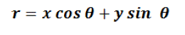
| The Hough Transform patented by Paul Hough in 1962 is basically a feature extraction method used to detect lines and finding arbitrary shapes position in the image and is used in the field of computer vision and image processing. Related to this patent, Richard Duda and Peter Hart in 1972 invented the Hough Transform which is used today and they named it „Generalized Hough Transform?. A line can be described in the image space as | ||||||||||||||||||||||||||||||||||||
| Figure 4 shows the main idea in Hough transform. All straight lines passing through point (x, y) satisfy that equation but the values of slope m and intercept c may vary. Now instead of considering the point (x, y), parameters (m, c) are considered to understand the characteristics of straight lines in the image. This is the main idea in Hough Transform. If vertical lines are present in the image the values of m will be infinity, so use parameters (r, θ). The parameter r represents the distance between line and origin, θ is the angle of the vector from origin to this point. So the new rearranged equation becomes | ||||||||||||||||||||||||||||||||||||
 (2) (2) |
||||||||||||||||||||||||||||||||||||
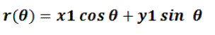
| For any arbitrary point in the image plane coordinates, e.g. (x1, y1) the lines that go through are | ||||||||||||||||||||||||||||||||||||
 (3) (3) |
||||||||||||||||||||||||||||||||||||
| This forms a sinusoidal curve in the (r, θ) plane, which is unique for that particular point. Now, more generally a set of points which form a straight line will produce curves which cross at the (r, θ). The result of the Hough transform is stored in a matrix that often called an accumulator. One dimension of this matrix is the θ values (angles) and the other dimension is the r values (distances), and each element has a value telling how many points/pixel that lie on the line with the parameters (r, θ). So the element with the highest value tells what line that is most represented in the input image. Hough Transform has an advantage which is that the point need not all be continuous. This can be really helpful if line is broken due to noise. One more factor to be considered is the efficiency which depends on the quality of input data. It also has an importance in the skew correction of documents and characters, finding shapes like rectangle, circle, ellipse etc. in the image. | ||||||||||||||||||||||||||||||||||||
SUB-PIXEL EDGE DETECTION |
||||||||||||||||||||||||||||||||||||
| Sub-pixel edge detection simply means that detecting edges at sub-pixel level. The problem is that if the barcode image is blurred than the width of white space and black space gets merged. So it becomes a tough task to find out the edges at pixel level. Hence sub-pixel edge detection method is preferred to detect edges in barcode. When a white line is viewed on black background, the pattern obtained is an ideal step-shaped waveform. But in real life the image is blurred so the waveform is not ideal. This blurring will result into a Gaussian curve. And to detect positive and negative edges in that is too complex. | ||||||||||||||||||||||||||||||||||||
| Figure 5 shows the ideal barcode and its pattern. It can be observed from the figure that the pattern contains only two points either it is 0 or it is 1. Now the effect of blurred edges will be fading of sharp edges in derivative signal. So locating edges becomes even more difficult. In scanning precision is needed to get true 13 digit barcode. This Algorithm gives good precision. | ||||||||||||||||||||||||||||||||||||
| Figure 6 shows the real barcode and its pattern which is not the same as that of ideal barcode. It is much like a Gaussian curve | ||||||||||||||||||||||||||||||||||||
| The algorithm is described below. | ||||||||||||||||||||||||||||||||||||
| Part 1: As in the theoretical case, the point-to-point derivate function is calculated. This function has only valid values on the sample moments of the original values. | ||||||||||||||||||||||||||||||||||||
| Part 2: Calculate the second order derivative. | ||||||||||||||||||||||||||||||||||||
| Part 3: The cubic interpolation technique is used to create a continuous function out of the sample values obtained in step 2. | ||||||||||||||||||||||||||||||||||||
| Part 4: To know the exact position of the positive and negative edge, the zero-crossing position for the function from part 3 has to be determined. | ||||||||||||||||||||||||||||||||||||
| Figure-7 shows different steps in sub-pixel edge detection. The goal here is to determine the exact edges in a blurred barcode image. The method is to take out sample-view cross sections of an arbitrary line which contain a single row of barcode which is shown by blue colour in the figure. Then next step is to calculate the first order derivative of the sample points and it is shown in figure by pink points. The edges are located at the maximum and minimum of this derivative function. These positions are determined by calculating second order derivative shown in figure by green points. Here the edges are located at zero crossings of this function. To determine those positions with precision this function is interpolated in the fourth part. Interpolation is shown in implementation part. | ||||||||||||||||||||||||||||||||||||
| Figure 8 shows the actual first and second order derivative of the barcode. The pink points are the first order derivative and the green are the second order derivative. Figure 9 shows the actual zero crossing detection. The red arrows show the point where the interpolation curve is crossing zero. | ||||||||||||||||||||||||||||||||||||
MATLAB IMPLEMENTATION |
||||||||||||||||||||||||||||||||||||
| In any image containing barcode, there can be a possibility that the barcode is skewed. So the angle at which the barcode is skewed must be found and corrected. It is done using Hough Transform [10] [11]. In regular scanning using Laser Scanner the object containing the barcode must be held in horizontal position and stationary. The good thing about this scanning is the time which it takes. As stated earlier we have done this work for a camera based system. So to hold the object horizontal and stationary is not convenient for any real-time system. So we have used here Hough Transform which will correct the skewed barcode which in turn assist in accurate scanning. | ||||||||||||||||||||||||||||||||||||
| MATLAB has inbuilt function for Hough transform which are hough, houghpeaks and houghlines. Those functions are described earlier in this thesis. Hough transform?s function in MATLAB are able to detect angle within the range -90° to 90°. We have considered here two cases on skewed image which can be in the 1st and 4th quadrant (range is -90° to 90°). The main problem faced is that the angle output which was obtained after applying Hough Transform was not standard i.e. if image is skewed at 30°, the output will show some more angles including 30°. So the main task is to find out the angle at which the image is skewed actually. Then only it can be corrected accurately. And it did not give accurate result with all the images. So it was not tolerable. I decided to form new functions to make it accurate enough for any image. Then I started writing new functions to make the system error proof. On the way I realised some more constraints which were giving wrong output. Finally I came up with the solution. I created four functions which are explained below. | ||||||||||||||||||||||||||||||||||||
| Function 1: It will take skewed image as an input and will give the angles of the lines plotted in the image. | ||||||||||||||||||||||||||||||||||||
| Step 1: Take the skewed sample image as input | ||||||||||||||||||||||||||||||||||||
| Step 2: Convert it into black and white image | ||||||||||||||||||||||||||||||||||||
| Step-3: Apply edge detection to that image | ||||||||||||||||||||||||||||||||||||
| Step 4: Apply hough transform | ||||||||||||||||||||||||||||||||||||
| Step 5: Find hough peaks | ||||||||||||||||||||||||||||||||||||
| Step 6: Plot hough lines | ||||||||||||||||||||||||||||||||||||
| Step 7: Get the angles of those linesFunction 2: It will take output of the function 1 (angles) and find the no. of occurrences of each angle. It gives a matrix which contains each angle at least one time as output. | ||||||||||||||||||||||||||||||||||||
| Step 1: Take angle found as input | ||||||||||||||||||||||||||||||||||||
| Step 2: Initialize an array to store the occurrence of the angle | ||||||||||||||||||||||||||||||||||||
| Step 3: Put the angle occurred at least once in the arrayFunction 3: This function is created to support angel correction. It will give a matrix which shows the number of zero angles occurred.Step 1: Take angles as inputStep 2: Find the number of zero angles is the input matrix | ||||||||||||||||||||||||||||||||||||
| Function 4: This is the main angle correction function. It takes skewed image as input. It is followed by the above three function created. With the help of all three functions, this function tries to correct angle until a certain value of zero angle is achieved. This zero angle satisfies that the image is now completely corrected. It takes the angle input from the | ||||||||||||||||||||||||||||||||||||
| function 2 to correct the angle. Then if particular number of zeros are not achieved it takes the next angle and follows the same procedure. | ||||||||||||||||||||||||||||||||||||
| Step 1: Take input skewed image | ||||||||||||||||||||||||||||||||||||
| Step 2: Using function 1, 2 and 3 find the angles, angle occurrence and number of zero angles. | ||||||||||||||||||||||||||||||||||||
| Step 3: Check whether the number of zero angles are below of above a threshold specified (for example | ||||||||||||||||||||||||||||||||||||
| Step 4: If above condition is satisfied the rotate the image with angel (from angle occurrence array). If not then try with next angle from angle occurrence matrix. | ||||||||||||||||||||||||||||||||||||
| Figure 9 shows the skewed barcode image taken as a sample. Figure 10 shows the edge detection step applied on the sample skewed barcode image. | ||||||||||||||||||||||||||||||||||||
| Figure 11 shows the Hough transform of the sample barcode. Hough transform is applied on the edge detection. MALAB has inbuilt code for Hough transform. Figure 12 shows the hough lines which shows five lines in the skewed barcode image. We can specify more lines if required. Figure 13 shows the corrected barcode image. A code is written in MATLAB as explained in the steps. It gives an angle as an answer. The original sample image is rotated at the angle so that we can get the horizontal barcode in the image. | ||||||||||||||||||||||||||||||||||||
| Scanning of barcode is done to get 95 bits. Here I have used Sub-Pixel edge detection method to detect the edges in a real time blurred barcode image at sub-pixel level. I have successfully scanned image which are blurred up to a level where even human eye cannot recognise the edges. The code written to scan the image comprise of the function created earlier in 6.1.1. A directory can be provided by the user or image path can be directly written in the code. The steps are as follows. | ||||||||||||||||||||||||||||||||||||
| Step 1: Take input image | ||||||||||||||||||||||||||||||||||||
| Step 2: Find whether the image is 2D or 3D and convert it into black and whiteStep 3: Take out a single row which contains the full barcode | ||||||||||||||||||||||||||||||||||||
| Step 4: Remove the portion other than barcode from the row | ||||||||||||||||||||||||||||||||||||
| Step 5: Take first differentiation of the row array | ||||||||||||||||||||||||||||||||||||
| Step 6: Take out second differentiation | ||||||||||||||||||||||||||||||||||||
| 7: Interpolate the second differentiation | ||||||||||||||||||||||||||||||||||||
| 8: Store maximum and minimum value from that (here we go into sub-pixel) | ||||||||||||||||||||||||||||||||||||
| Step 9: Find out zero crossing points and store them | ||||||||||||||||||||||||||||||||||||
| Step 10: Compare each value of zero crossing with the maximum and minimum values stored earlier. Find out which are strong and weak edges. Keep strong edges and remove weak ones | ||||||||||||||||||||||||||||||||||||
| Step 11: Find out the width of thin bar (1st guard bar and last guard bar) | ||||||||||||||||||||||||||||||||||||
| Step 12: Store these four widths in an array | ||||||||||||||||||||||||||||||||||||
| Step 13: Find out which edges are of black bar and which are of white bar | ||||||||||||||||||||||||||||||||||||
| Step 14: Form one array which contains the widths of black or white bar | ||||||||||||||||||||||||||||||||||||
| Step 15: Form 1*95 bits considering the width and bar (white or black) | ||||||||||||||||||||||||||||||||||||
| Step 16: Give these bits to the function developed to decode the barcode | ||||||||||||||||||||||||||||||||||||
| Figure 14 shows the real time blurred barcode image on which the sub-pixel edge detection algorithm is applied. Figure 15 shows the Grayscale image. Then a sample row is taken mostly the middle row which is shown in figure 16. | ||||||||||||||||||||||||||||||||||||
| Figure 17 shows the first order derivation of the sample row taken. Figure 18 shows a plot containing the sub-pixel interpolation from which the zero crossings are found and actual edges are detected. | ||||||||||||||||||||||||||||||||||||
CONCLUSION |
||||||||||||||||||||||||||||||||||||
| Some constraint occurred during this development, like if the barcode is skewed at an angle more than 180 i.e. if it is in 3rd or 2nd quadrant then its angle detection using Hough transform is difficult. Other important constraint is that if the size of image is changed then the software faces problems to scan the barcode. As previously described here that software faces problems with real time blurred images is fully solved. Now it can scan accurately both ideal and realtime images. Some problems occurred with angle correction part like the software was not able to correct the angles like 5, 17, 29 etc. and it was accurately correcting angles like 10, 20, 30, 40, 50 etc. But now I have made some modifications in the code and functions so that it can solve the problem. A problem with GUI is that camera snap shot image cannot be recognized as laptop camera is not so high resolution camera. One more thing is that holding the barcode containing object in hand faces vibration problems so image is not steady. These images are not scanned. As I have included camera in GUI just for demo purpose. I have also created functions like to process image before scanning, blur image, etc. The better part of the software is it does not take much time to execute and give result. So this logic used in the code can be used to develop a real-time system in industry. Further modifications in the code and GUI can be done according to the need of the user. | ||||||||||||||||||||||||||||||||||||
Tables at a glance |
||||||||||||||||||||||||||||||||||||
|
||||||||||||||||||||||||||||||||||||
Figures at a glance |
||||||||||||||||||||||||||||||||||||
|
||||||||||||||||||||||||||||||||||||
References |
||||||||||||||||||||||||||||||||||||
|


