Keywords
|
| RFID-Radio frequency Identification, EPC-Electronic Product Code,C1G2-Class 1 Generation 2,ARM-Advance RISC Machine |
INTRODUCTION
|
| RADIO-FREQUENCY identification (RFID) is a contact-less identification technology that enables remote and automated Gathering and sending of information between RFID tag’s or transponders and readers or interrogators using a wireless link. In recent years, RFID technology has gained a rapid acceptance as a means to identify and track a wide array of manufactured objects. It is composed of three main components: tag, reader and Server. |
| RFID tag’s come in a range of forms and can vary in storage capacity, memory type, radio frequency and power capability. Most of these tag’s contain only a unique Electronic Product Code(EPC) number and further information about the product is stored on a network of databases, called the EPC-Information Services(EPC-IS).Through the wireless interface, each tag can report data when queried over radio by an RFID reader. |
| RFID readers can only recognize tag’s in proximity; a data tag that is out of range cannot be read by a reader. Secured Authentication protocol is described in this paper. The rest of this paper is organized as follows. In Section 1, we present the Background and previous work in the RFID reader-to-tag authentication protocol in section 2. The enhanced pad generation (PadGen) function is discussed in Section 3. Section 4 shows implementation results of the proposed mutual authentication scheme. Finally, we conclude this paper in Section 5. |
EPC GLOBAL CLASS-1 GENERATION-2 STANDARD
|
| The EPC global Class-1 Generation-2 (C1G2) ultra-high frequency (UHF) RFID standard defines a specification for passive RFID technology and is an open and global standard. The EPC C1G2 standard specifies the RFID communication protocol within the UHF spectrum (860 to 960MHZ).The standard specifies that a complaint RFID tag should contain a 32-bit kill password (Kpwd) to permanently disable the tag and a 32-bit access password (Apwd). The reader then performs a bitwise XOR of the data or password with a random number from the tag to cover coded data or a password in EPC Gen 2. |
COMPONENTS OF AN RFID SYSTEM
|
| The RFID system consists of various components which are integrated. This allows the RFID system to deduct the objects (tag) and perform various operations on it. The integration of RFID components enables the implementation of an RFID solution. The RFID system consists of following three components |
| • Tag (attached with an object, unique identification). |
| • Reader (receiver of tag information, manipulator). |
| • Server (overall information about the tag and the manufacturer). |
| A) Tag’s |
| Tag’s contain microchips that store the unique identification (ID) of each object. The ID is a serial number stored in the RFID memory. The chip is made up of integrated circuit and embedded in a silicon chip. RFID memory chip can be permanent or changeable depending on the read/write characteristics. Read only and rewrite circuits are different as read-only tags contain Fixed data and cannot be changed without re-program electronically. On the other hand, re-write tags can be programmed through the reader at any time without any limit. There are three types of tag’s the passive, semi-active and active. Semi-active tags have a combination of active and passive tag’s characteristics. So, mainly two types of tag’s (active and passive) are being used by industry and most of the RFID system. |
| B) Reader |
| RFID reader works as a central place for the RFID system. It reads tag’s data through the RFID antennas at a certain frequency. Basically, the reader is an electronic apparatus which produce and accept a radio signals. The antennas contains an attached reader, the reader translates the tag’s radio signals through antenna, depending on the tag’s capacity. The readers are expected to collect or write data on to tag (in case) and to pass computer systems. |
| C) RFID System |
| The RFID tag’s 32-bit Access password and 32-bit kill passwords achieve tag–reader mutual authentication. Their scheme uses two rounds of PadGen to compute a cover-coding pad. The first round performs PadGen over the access password, while the second round performs PadGen over the kill password. The PadGen function is used to create the 16-bit pads for “cover coding” the access password. |
| D) A Stepwise description of RFID System |
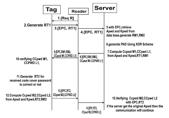
| 1. The reader issues a Req_RN command to the acknowledged tag. |
| 2. The tag then generates two 16-bit random numbers, namely, RT1 and RT2, and backscatters them with its EPC to the reader. The reader forwards these messages to the manufacturer. |
| 3. The manufacturer matches the received EPC to retrieve the tag’s access password (Apwd) and kill password (Kpwd) from the back-end database. |
| 4. The manufacturer then generates and stores two 16-bit random numbers, namely, RM1 and RM2. The “cover-coded passwords” for the 16-bit MSBs (CCPwdM1) and the 16-bit LSBs (CCPwdL1) are computed by the PadGen function. |
| 5. CCPwdM1, CCPwdL1, and EPC along with four 16-bit random numbers, namely, RM1, RM2, RM3, and RM4, generated by the manufacturer are transmitted to the reader, which, in turn, forwards them to the tag for verification. |
| 6. To authenticate the tag, the tag generates another two random numbers RT3 and RT4 along with the received RM3and RM4 used to compute CCPwdM2 and CCPwdL2 with the PadGen (RTi,RMi) function. |
| 7. CCPwdM2, CCPwdL2, and EPC along with two 16-bit random numbers, namely, RT3 and RT4, are transmitted to the reader, which, in turn, forwards them to the manufacturer for verification. |
AUTHENTICATION SCHEMES
|
| Today security is imperative in many network-based applications. When dealing with data transfer, it is crucial to determine whether the data that is being received has been corrupted. In this system, we propose an authentication protocol, which mutually authenticates readers and tag's. It can resist man-in-the-middle attacks and reduce re- authentication overhead. The main advantage of our proposed scheme is that it does not require the implementation of any special cryptographic hash functions/keys within the tag. There is also no need for the tag and the reader to synchronize security keys/hash values. We propose to improve the existing one-way reader-to-tag authentication scheme. |
| E) Padgen |
| This scheme utilizes the tags 32-bit access and kill password in achieving tag-reader mutual authentication scheme. It uses two rounds of PadGen to compute a cover-coding pad. The first round performs PadGen over the access password, while the second round performs PadGen over the kill password. |
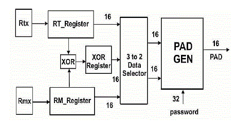
| The PadGen function is used to create the 16-bit Pads for covercoding the access password. This scheme is also much more dicult for an adversary to recover the access password under the correlation attack or to forge successful authentication under the dictionary attack.The PadGen function is the key function used to produce a cover-coding pad to mask the tags access password before transmission. The implementation of the PadGen function also requires the random number generator to produce RTx and RMx. |
| The PadGen function is used to create the 16-bit Pads for covercoding the access password. This scheme is also much more dicult for an adversary to recover the access password under the correlation attack or to forge successful authentication under the dictionary attack.The PadGen function is the key function used to produce a cover-coding pad to mask the tags access password before transmission. The implementation of the PadGen function also requires the random number generator to produce RTx and RMx. |
| F) Access Password |
| An access password is required before data are exchanged between a reader and a single tag. The access password is a 32-bit value stored in the tag's reserved memory. If this password is set, then the reader has to have the valid password before the tag will engage in a secured data exchange. |
| G) Kill Password |
| The access passwords can be used in activating kill commands to permanently shut down tag's, as well as for accessing and re locking a tag's memory. |
| H) Data Selector |
| In electronics, a multiplexer or mux is a device that selects one of several analog or digital input signals and forwards the selected input into a single line. A multiplexer of 2n inputs has n select lines, which are used to select which input line to be sent to the output.An electronic multiplexer makes it possible for several signals to share one device or resource.A multiplexer is often used with a complementary demultiplexer on the receiving end. Multiplexer are combinational logic switching devices that operate like a very fast acting multiple position rotary switch. They connect or control, multiple input lines called "channels" consisting of either 2, 4, 8 or 16 individual inputs, one at a time to an output. Then the job of a multiplexer is to allow multiple signals to share a single common output.Multiplexers are used as one method of reducing the number of logic gates required in a circuit or when a single data line is required to carry two or more different digital signals.Generally, multiplexers have an even number of data inputs, a number of "control" inputs that correspond with the number of data inputs and according to the binary condition of these control inputs, the appropriate data input is connected directly to the output. |
XOR SCHEME
|
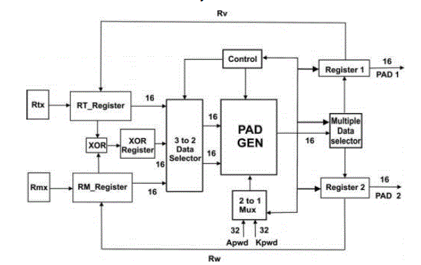
| In XOR Scheme each Pad function is computed based on PAD Function using one set of (RTx,RMx), which is transmitted in the open space. In contrast to the PadGen the present proposed PAD function is computed based on one set of (RV ,RW), which is not transmitted openly. |
| RV and RW are computed based on Apwd-PadGen (RTx,RMx)and Apwd PadGen(RTx,RTxRMx),respectively. PAD1 and PAD2 are then generated by Kpwd-PadGen(RV,RW)and Kpwd PadGen(RV,RvRW),respectively. The RV and RW values were calculated within the tag's and readers.Therefore,an adversary would not be able to correlate all the bits in ApwdM and ApwdL. |
| I) Implementation of XOR Scheme |
| In each PAD function is computed based on one set of (RTx,RMx), which is transmitted in the open space. In contrast to the PadGen proposed by Konidala et al., the present proposed PAD function is computed based on one set of (RV ,RW), which is not transmitted openly. RV and RW are computed based on Apwd-PadGen(RTx,RMx) and Apwd-PadGen(RTx,RTx ⊕ RMx), respectively. |
| PAD1 and PAD2 are then generated by Kpwd-PadGen(RV,RW) and Kpwd-PadGen(RV,RV⊕RW), respectively. The RV and RW values were calculated within the tag’s and readers. Therefore, an adversary would not be able to correlate all the bits in ApwdM and ApwdL. |
| 1. Apwd-PadGen(RTx,RMx)=dv1dv2dv3dv4=RV.RTx,RMx,and Apwd are selected as the inputs for PadGen operation,and the calculation results RV by XOR-PadGen operation are stored in register for further manipulation. |
| 2. Apwd-PadGen(RT,RT ⊕RM)=dw1dw2dw3dw4=RW. Through mux selection, RT , RT ⊕ RM, and Apwd are chosen as inputs for PadGen operation. The calculation result RW is stored in register for further computation. |
| 3. Kpwd-PadGen (RV,RW) = hq1hq2hq3hq4=PAD1. The PAD1 can then be obtained by mux selecting RV, RW, and Kpwd as inputs for XOR-PadGen operation. |
| 4. Kpwd-PadGen(RV,RV⊕RW)=hr1hr2hr3hr4=PAD2. Similarly, the PAD2 can then be obtained using RV,RV ⊕ RW, along with Kpwd for XOR-PadGen operation. |
MOD SCHEME
|
| Modulo arithmetic is used as another approach to generate the PadGen function because of the schemes simplicity.Modulo arithmetic does not require carry or borrow operations.In computing hardware, the carry circuitry is a major part of arithmetic computation and is a major contributor to speed limitations. The simplicity of modulo arithmetic allows several different approaches not available in the previous generation of PadGen function. These operations are done on modulo arithmetic based on modulo 2. |
| In modulo-2 mathematics, the subtraction function is replaced by the XOR operation. The XOR-based division (no carry in addition or subtraction) consumes very small resources. The particular advantage of XOR operation is that it can thus achieve low-cost hardware implementation of the PadGen function. |
| J) Implementation of MOD Scheme |
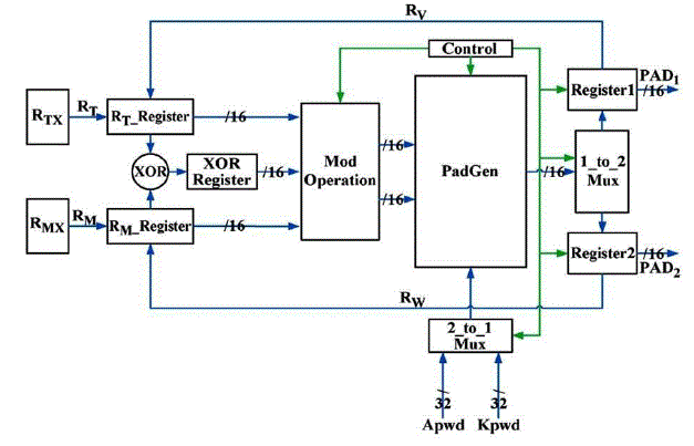
| To implement the PadGen operation based on modulo arithmetic, a modulo-2 circuit module is inserted before PadGen operation. After RTx and RMx are generated, a multiplexer was utilized to allow an Apwd or Kpwd to be selected for MODPadGen operation.The details of the functions performed are described as follows. |
| 1) Apwd-PadGen(RA,RB) = di1di2di3di4 = RI. The mod1 and mod2 listed in are used to generate RA and RB, respectively. |
| 2) RI is then calculated by performing PadGen over the Apwd, and the results are stored in Register1 for further manipulation. |
| 3) Apwd-PadGen(RC,RD)=dj1dj2dj3dj4=RJ. The mod3 and mod4 listed are used to generate RC and RD, respectively. RJ is then obtained by executing PadGen over the Apwd, and the results are stored in Register2 for further calculation. |
| 4) Kpwd-PadGen(RE,RF)=dk1dk2dk3dk4=PAD1. PAD1 is then calculated by performing PadGen over the Kpwd. |
| 5) Kpwd-PadGen(RG,RH)=do1do2do3do4=PAD2. PAD2 is then calculated by performing PadGen over the Kpwd. |
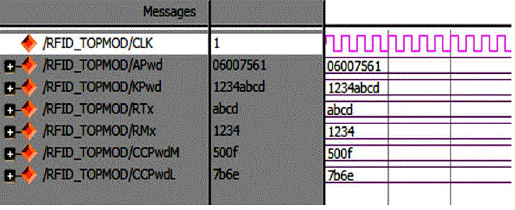
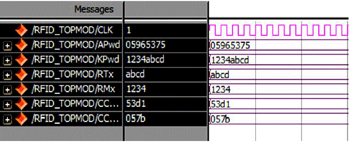
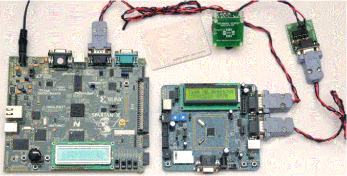
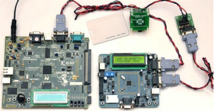
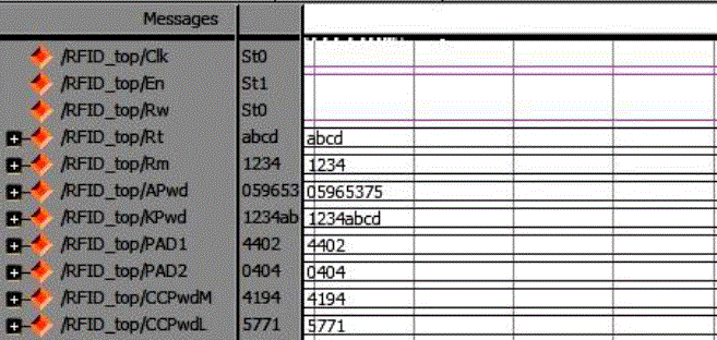
| Simulations of the proposed design were conducted in the Spartan 3E environment. The verified Verilog code was then downloaded on a Xilinx Spartan 3E FPGA running with a 50-MHz clock in the Spartan 3E board to verify the hardware. The output waveforms are displayed using ModelSim for real-time verification. The FPGA implementation result on the Spartan 3E and ARM 7 are shown in Fig. 7 and Fig 8. The LCD displays were used to denote the 16-b random numbers RT = abcd and RM =1234 , and the cover-coded Apwd =05965375 as shown in Fig. 7, The Verilog simulation results under the same input conditions as for FPGA implementation are shown in Fig.5 and Fig 6. Only Simulation verification done in Modelsim for MOD operation are shown in Fig 9. |
CONCLUSION
|
| To improve the security level of the original reader-to-tag authentication protocol proposed under the EPC C1G2 speciation, the PadGen functions are used to protect the Access password against exposure. The main advantage of the proposed scheme is that it does not require the implementation of any special cryptography hash functions/keys within the tag and a center server/database. The PadGen functions based on XOR operation and MOD operation in association with the tags Apwd and Kpwd are used to generate the PADi. The proposed protocol using the manipulated values within the tag's and reader to enhance the PadGen operation is more security for mutual authentication for the tag and reader.In Future Hash Functions for every components and it make more complexity to hack the password during the data transactions |
Figures at a glance
|
 |
 |
 |
 |
 |
| Figure 1 |
Figure 2 |
Figure 3 |
Figure 4 |
Figure 5 |
 |
 |
 |
 |
| Figure 6 |
Figure 7 |
Figure 8 |
Figure 9 |
|
| |
References
|
- Mohanavelu.S and Ramya.T, "Secured Authentication Protocol for RFID System Using XOR Scheme", IJSR - INTERNATIONAL JOURNAL OFSCIENTIFIC RESEARCH,Vol 2,No.5,May 2013
- Yu-Jung Huang, Senior Member, IEEE, Wei-Cheng Lin, and Hung-Lin Li, "Efficient Implementation of RFID Mutual Authentication Protocol",IEEE transactions on industrial electronics, vol. 59, no. 12, december 2012.
- Y. J. Huang, C. C. Yuan, M. K. Chen, W. C. Lin, and H. C. Teng, "Hardware implementation of RFID mutual authentication protocol",IEEE Trans.Ind. Electron., vol. 57, no. 5, pp. 15731582, May 2010.
- S. Piramuthu, "Lightweight cryptographic authentication in passive RFID-tagged sys- tems", IEEE Trans. Syst., Man, Cybern. C, Appl. Rev.,vol. 38,no. 3, pp. 360376, May 2008.
- A.Juels, "RFID security and privacy: A research survey", IEEE J. Sel.AreasCommun.,, vol. 24, no. 2, pp. 381394, Feb.2006.
|