ISSN ONLINE(2320-9801) PRINT (2320-9798)
ISSN ONLINE(2320-9801) PRINT (2320-9798)
V.Naga Arjun, Dr. D.Nagarathinam
|
| Related article at Pubmed, Scholar Google |
Visit for more related articles at International Journal of Innovative Research in Computer and Communication Engineering
This project “AUTOMATIC GENERATE CNC CODE FOR SYMMETRICAL OBJECT” mainly focuses in cloning any symmetrical object from any remote area. First, software is created which is meant to generate CNC codes for lathe automatically and it sends the generated codes to any part of the world with the help of internet in a fraction of second, this also can be said as live object transfer. The software has a scanning window which is used to scan the object and to find the dimensions of the object. The object is captured using a video camera and stored as an image. This image is then scanned for its dimensions using image processing technique with the help of scanning software. These dimensions are used to write the special standardised codes meant for the CNC Lathe, the G & M codes. Hence the codes to make the object are generated. The generated codes are transferred through internet to any part of the world in a fraction of seconds. The specialty of this project is, the scanning, the automatic generation of CNC codes, sending the generated codes to any remote area all these things happens in a fraction of seconds.
Keywords |
| Image processing,scanning window,object transfer |
INTRODUCTION |
| E-mail (electronic-mail) may be defined as sending mailing through internet; transferring money through internet is called e-commerce; buying a product through internet is called e-buy, like wise controlling machines with the help of internet is called e-control.In our project we are taking the advantage of using “e-control” to clone a symmetrical object in any remote area. High speed of code generation and the live object transfer are the next step development of automation. This project involves in developing software called “scanning window” for scanning the object to get its exact dimensions and to write CNC G and M codes automatically. The software is written in “visual basic” language |
CONSTRUCTION |
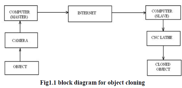
| The object is captured as an image with the help of a digital camera, the distance between the object and the camera is fixed by calibrating the image to get its original size. The image processing is done with a help of a computer and the scanning of the image is done by creating software called scanning window. The scanning consists of vertical scanning and horizontal scanning to get the dimensions of the object. The software also contains a code generator which generates the CNC codes automatically with the help of the scanned dimensions of the object. Then the generated codes are sent to the desired place with the help of internet by using client/server or master/slave technique. |
 |
WORKING PRINCIPLE |
| The object which is to be cloned is kept in a black background with perfect lightings. A high resolution digital camera is used to capture the image of the object; the resolution of camera will determine the quality of the image. The captured image is stored in a computer for image processing and scanning. The image is then scanned to get the dimensions of the object, scanning is done by creating software called scanning window which is written in visual basic language. The scanning consists of vertical scanning to determine the length of the object and horizontal scanning to calculate the height of the object. The method of determining the height and length of the object is clearly explained in the design calculations. The principle of scanning is by identifying the color of the pixels. The scanning gives the dimensions and coordinates of the object which is used in writing the CNC codes for CNC lathe automatically. The generated codes are sent to the desired location with the help of internet especially with client/server technique. |
MISCELLANEOUS FUNCTIONS |
| Miscellaneous functions, commonly called M-codes are specified by the address M followed by two-digit number. Mcodes instruct the control unit to generate signals for on/off control of machine functions. |
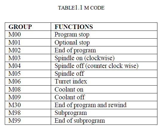 |
IMAGE PROCESSING TECHNIQUES |
| An image may be defined as a two dimensional function, f(x,y) where x and y are spatial (plane) coordinates, and the amplitude of f at any pair of coordinates(x,y) is called the intensity or gray level of the image at that point. When x,y and the amplitude values of f are all finite, discrete quantities, we call the image a digital image. The field of digital image processing refers to processing digital images by means of a digital computer. Note that a digital image is composed of a finite number of elements, each of which has a particular location and value. These elements are referred to as picture elements, image elements, pels, and pixels. Pixel is the term most widely used to denote the elements of a digital image. |
SCANNING WINDOW |
| The transmission side needs the dimensions of the object to be modelled in the CNC lathe. The dimensions can be obtained by scanning the image of the object to be transferred. For scanning, the image is obtained through a highresolution camera. Photographs are taken by placing the object over a dark or black background. |
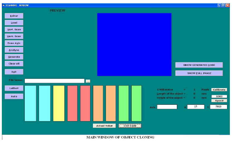 |
| Alternatively, we can sketch the shape of the object with required dimensions. The photographed image or the sketched diagram of the object forms the input in the transmission side. |
CALIBRATION |
| The captured image may be of any size which depends on the distance between the camera and the work piece. Hence the obtained image is not the original size of the object. To get the original size of the object it need to be calibrated for its original size. To calibrate the image first we are capturing a line, whose dimensions are known. The number of pixels of the captured image is counted first, since the dimensions of the image is known already equate it with the number of pixels. Therefore dimensions of a unknown object can be determined with the calibration. A photograph of a 10mm length line against a white background is taken. The photograph of the work piece has to be taken from the same fixed distance against a black background. By finding the number of pixels in the 10mm line, the original dimensions of the work piece are calculated. If there are „x‟ no. of pixels in 10mm length of a line then, the scale is calculated as „x\10‟ pixels/mm. To get the original dimensions in mm, it is divided by the scale. |
RGB COLOR MODEL |
| In the RGB model, each color appears in its primary spectral components of red, green, and blue. This model is based on a Cartesian coordinate system. The color subspace of interest is the cube in which RGB values are at three corners; cyan, magentas, and yellow are at three other corners; black is at the origin; and white is at the corner farthest from the origin. In this model, the gray scale (points of equal RGB values) extends from black to white along the line joining these two points. The different colors in this model are points on or inside the cube, and are defined by vectors extending from the origin. For convenience, the assumption is that all color values have been normalized so that the cube is the unit cube. That is, all values of R, G, B are assumed to be in the range [0,1]. |
| Images represented in the RGB color model consist of three component images, one for each primary color. When fed into an RGB monitor, these three images combine on the phosphor screen to produce a composite color image. The number of bits used to represent each pixel in RGB color pixel [that is, a triplet of values (R, G, B)] is said to have a depth of 24 bits (3 image planes times the number of bits per plane). The term full-color image is used often to denote a 24 bit RGB color image. The total number of colors in a 24- bit RGB image is (28)3= 16,777,216. The 24-bit RGB color cube corresponding to the diagram. |
| The cube shown in fig is a solid, composed of the (28)3=16,777,216 colors mentioned in the preceding paragraph. A convenient way to view these colors is to generate color planes (faces or cross sections of the cube). This is accomplished simply by fixing one of the three colors and allowing the other two parallel to the GB-plane is the plane (127, G, B) for G, B=0, 1, 2, …..,255. Here we used the actual pixel values rather than the mathematically convenient normalized values in the range [0,1] because the former values are the ones actually used in a computer to generate colors. Figure shows tat an image of the cross sectional plane is viewed simply by feeding the three individual component images into a color monitor. In the component images, 0 represents black and 255 represents white (note that these are gray scale images). Finally, figure shows the three hidden surface planes of the cube in figure generated in the same manner. |
| It is of interest to note that acquiring a color image is basically the process shown in figure in reverse. A color image can be acquired by using three filters, sensitive to red, green, and blue, respectively. When we view a color scene with a monochrome camera equipped with one of these filters, the result is a monochrome image whose intensity is proportional to response of that filter. |
| Repeating this process with each filter produces three monochrome images that are the RGB component images of the color scene. (In practice, RGB color image sensors usually integrate this process into a single device.) Clearly, displaying these three RGB component images in the form shown in figure would yield an RGB color rendition of the original color scene. |
| While high-end display cards and monitors provide a reasonable rendition of the color in a 24-bit RGB image, many systems in use today are limited to 256 colors. Also, there are numerous applications in which it simply makes no sense to use more than a few hundred, and sometimes fewer, colors. Given the variety of systems in current use, it is of considerable in-son ably independently of viewer hardware capabilities. This subset of colors is called the set of safe RGB colors, or the set of all-systems-safe colors. In internet applications, they are called safe Web colors or safe browser colors. |
 |
| On the assumption that 256 colors is the minimum number of colors that can be reproduced faithfully by any system in which a desired result is likely to be displayed, it is useful to have an accepted standard notation to refer to these colors. Forty of these 256 colors are known to be processed differently by various operating systems, leaving only 216 colors that are common to most systems. |
| These 216 colors have become the de facto standard for safe colors, especially in Internet applications. They are used whenever it is desired that the colors viewed by most people appear the same. Each of the 216 safe colors is formed from three RGB values as before, but each value can only be 0, 51, 102, 153, 204, or 255. Thus, RGB triplets of these values give us (6)3= 216 possible values (note that all values are divisible by 3). It is customary to express these values in the hexagonal number system, as shown in table. Recall that hex numbers 0, 1, 2,….,9 , A, B, C, D, E, F correspond to decimal numbers 0,1,2…..,9, 10, 11, 12, 13, 14, 15 . Recall also that (0)16= (0000)2 and (F)16=(1111)2. Thus, for example, (FF)16=(255)10=(11111111)2 and we see that a grouping of two hex numbers forms an 8-bits byte. Since it takes three numbers to form an RGB color, each safe color is formed from three of the two digit hex numbers in Table 6.1 for example, the purest red is FF0000. The values 000000 and FFFFFF represent black and white, respectively. Keep in mind that the same result is obtained by using the more familiar decimal notation. For instance, the brightest red in decimal notation has R= 255 (FF) and G=B=0. |
| The 216 safe colors, organized in descending RGB values. The square in the to left array has value FFFFFF (white), the second square to its right has value FFFFCC, the third square has value FFFF99, and so on for the first row. The second row of that same array has values FFCCFF, FFCCCC, FFCC99, and so on. The final square of that array has value FF0000 (the brightest possible red). |
| The second array to the right of the one just examined starts with value CCCCCC and proceeds in the same manner, as do the other remaining four arrays. The final (bottom right) square of the last array has value 000000(black). It is important to note that not all possible 8-bit |
DETERMINING THE COORDINATES |
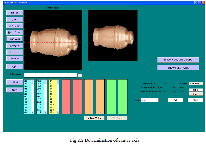
| The programming for CNC lathe can be done by measuring the size and determining the coordinates of the object. The height and length of the object can be calculated by a method as said above. The captured image is in black background, by scanning this image in pixel wise the change in color is marked which gives the first coordinate. The vertical scanning will give the coordinates of the object in length wise, scanning horizontally will give the coordinates of the object in height wise. The change in the color of pixel in black back grounded object is marked down which gives the coordinates of the object. |
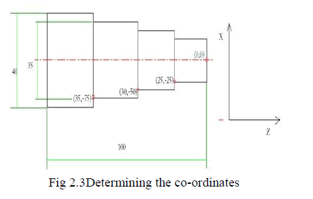 |
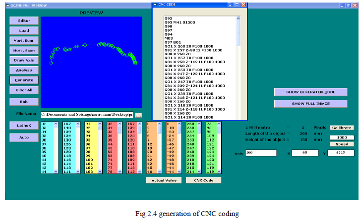
| The required coordinate for writing G and M codes is marked and shown above. In CNC programming the initial few steps are common lines and final few steps are common lines. The main machining lines needs the above marked points hence these coordinates are used in writing the CNC G and M codes. |
 |
MODERM COMMUNICATION |
| A modem, Modulator Demodulator, is a device that is connected to the computer and the telephone lines, allowing the computer to transmit data to (or receive data from) a similarly equipped remote computer. The modulator portion of the modem converts the digital signals from computers into telephone-line-compatible analogue signals. The demodulator portion of the modem receives the analogue signals and converts them to digital signals, readable by computers. The main technique used in the modem is the Frequency Shift Keying by which the above conversions are made possible. |
CLIENT-SERVER MODEL |
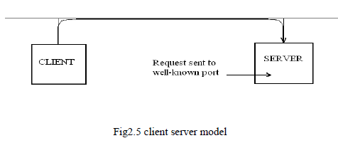
| A server is a computer program that offers a service over a network. A server accepts an incoming request, forms a response, and returns the result to the requester. For the simplest services, each request arrives in a single datagram and the server returns a response in another datagram. |
| An executing program becomes a client when it sends a request to a server and waits for a response. Because the client-server model is a convenient and natural extension of inter process communication used on a single machine, it is easy for programmers to build programs that use the model to interact. |
 |
| Servers can perform simple or complex tasks. For example, a time-of-day server merely returns the current time whenever a client sends the server a packet. A web server receives requests from a browser to fetch a copy of a Web page; the server returns the requested page to the browser. |
| Usually, servers are implemented as application programs. The advantage of implementing servers as application programs is that they can execute on any computing system that supports TCP/IP communication. For example, if theload on a server increases, the server can be moved to a faster CPU. Technologies exist that allow a server to be replicated on multiple physical computers to increase reliability or performance. |
ADVANTAGES |
| • Live object transfer. |
| • Eliminates the transportation cost. |
| • Eliminates the transportation time. |
| • Reduces the downtime. |
| • Increases the productivity. |
| • No need of CNC programmer. |
| • Reduces the time required for writing CNC codes. |
| • Contour objects can be cloned easily. |
| • The scanning of object takes place in pixel wise; hence a very good accuracy can be obtained. |
| • Any kind of objects can be cloned and transferred in a fraction of seconds. |
LIMITATIONS |
| • Characteristics of cloned object depend on resolution of digital camera. |
| • Only symmetrical objects can be cloned. |
APPLICATION |
| This project object cloning can be applied in, |
| CNC based industries. |
| Mass production. |
| Automobile industries. |
| Ship building industries. |
| Aircraft parts manufacturing industries. |
FUTURE DEVELOPMENT |
| Complicated components can also be cloned by developing the software to scan three-dimensionally. The software can further be developed to clone any asymmetrical objects. Objects with threads can be cloned and transferred by measuring the pitch and number of threading. |