International Journal of Advanced Research in Electrical, Electronics and Instrumentation Engineering
ISSN ONLINE(2278-8875) PRINT (2320-3765)
ISSN ONLINE(2278-8875) PRINT (2320-3765)
| Poonam Borle, Ankita Saswadkar, Deepali Hiwarkar, Rupali S. Kad Dept. of E&TC, Pimpri Chinchwad College of Engineering, Pune, Maharashtra, India |
| Related article at Pubmed, Scholar Google |
Visit for more related articles at International Journal of Advanced Research in Electrical, Electronics and Instrumentation Engineering
As in every where automation is required to reduce the work so we decided to implement to automatic meter reading using power line communication. AMR is the modern Power measuring device .It is being used in measuring electricity , gas , water consumption in many countries on the world since it has a lot of advantages that the old analog meters doesn’t have. It has advantages in safety , real time measuring and time saving as well as it has a better user interface and digital data analysis .Data is send over existing carrier thats reduces the complexity and cost of system.
Keywords |
||||||||
| AMR, PLC, PLCC. | ||||||||
INTRODUCTION |
||||||||
| Power is the soul of world which is related to the electricity and “electricity” is the word which now rules the world. So, proper utilization of this commodity is of immense important to us. Hence, it is necessary to measure power consumption. Normally, large scale industries consist of various departments like production, storage, package, administration, transportation situated away from each other. For such industries, it is necessary to maintain record of daily power consumed by every department to keep check on excess power consumed. | ||||||||
| A power line carrier (PLC) communication system operating on a conventional three wire (Hot (H), Neutral (N) and Ground (G) wires) power line uses more than one of the several RF transmission lines that are defined by the three wire power line to improve communication between units of the PLC system. According to a first embodiment a PLC system transmitter sends out of phase RF signals across the H and G wires and across the N and G power wires to the PLC system receiver, which receives and combines both of the out of phase transmissions, and so even if one of these paths is severely attenuated, the other path can deliver a sufficiently strong RF signal to the receiver for effective communications. According to another embodiment three different pairs of the H, N and G wires of the power line are selected in sequence for transmission of the PLC system RF and the pair that results in the best communication between a system transmitter and receiver is used for continuing communication. Also included is a PLC telephone extension system for which there is full duplex communication between each of the extension telephones of the system at different locations in the premises and the premises telephone line. | ||||||||
LITERATURE SURVEY |
||||||||
| AMR (Automatic Meter Reading ) is the modern Power measuring device .it is being used in measuring electricity , gas , water consumption in many countries on the world since it has a lot of advantages that the old analog meters doesn’t have . | ||||||||
| It has advantages in safety , real time measuring and time save as well as it has a better user interface and digital data analysis . | ||||||||
| AMR appears in several types depends on measured data type and data transfer technologies . We can say that AMR is the best solution to measure , collect and analyze data for the Mega networks like the electricity transmission and distribution network in Egypt . | ||||||||
| In 1886 , the first ac transmission line was installed . Since this age , it was very important to measure the energy that consumers pay for . Hence , the first generation of power meters was found which we know as (Watt-Hour meter ) [1]. | ||||||||
| As most of us know , the first generation(traditional meter reading devices ) is being used tell now in many places .It has a lot of disadvantages that we will mention later . | ||||||||
| To overcome this disadvantages we have to modify a new reading system that provides remote reading , safety , on-time readings and a simple user interface . That is what AMR provides successfully . | ||||||||
| The first AMR system was created on 1974 on USA by Mr. Paraskevakos who used a technology developed on 1972 by Theodore George. | ||||||||
BLOCK DIAGRAM |
||||||||
? Block Diagram Explanation |
||||||||
1. Power supply: |
||||||||
| • In the circuit using IC 7805, we can get +5V DC supply. | ||||||||
| • In the circuit, +5V DC supply is required for : | ||||||||
| ? AVR ATMEGA16 | ||||||||
| ? LCD Display | ||||||||
| ? Zero crossing detector | ||||||||
| ? Power line communication IC TDA5051 | ||||||||
2. AVR ATMEGA16: |
||||||||
| The AVR is the heart of the system. It controls the LCD display, generates interrupts, and controls the power line communication unit. | ||||||||
3. Energy meter: |
||||||||
| An electronic device that measures the amount of electrical energy supplied to a residence or business. It is electrically fed and composed of electronic controllers. It incorporates an interface which allows data to be transmitted from the remote terminal to the isolator block. | ||||||||
4. LCD Display: |
||||||||
| LCD means Liquid Crystal Display. It is a display device which displays the information provided to it. Its shape and size varies from application to application. | ||||||||
| LCD used in our project is 16 X 2 display in which 16 implies no. of characters and 2 implies no. of rows. It also provides wide range of display functions. It also provides low power consumption. It displays the number of units of energy transmitted . | ||||||||
5.Optocoupler IC MCT2E: |
||||||||
| In our project, we need to provide electrical isolation between them. This isolation is provided by the signal conditioner circuit which is actually MCT2E. | ||||||||
6. Power line communication IC TDA5051: |
||||||||
| The communication between transmitter unit and receiver unit is done through the AC power line. For this power line communication equipment is implemented which works as a modem. This modem IC, TDA 5051 supports ASK transmission. | ||||||||
7. Computer: |
||||||||
| The final reading is display on computer and total cost of meter reading is display on computer by using serial communication. The output is display on PC using Visual Basics 6.0 version. | ||||||||
OVERVIEW OF OUR PROJECT |
||||||||
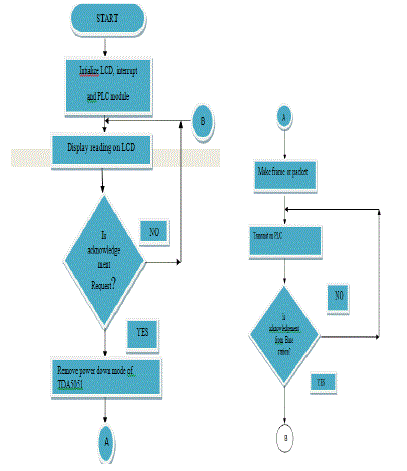
| ? FLOW CHART FOR ENERGY METER: | ||||||||
 |
||||||||
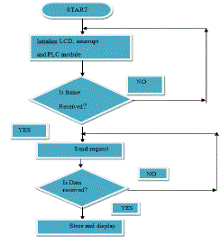
| ? FLOWCHART FOR BASE STATION | ||||||||
 |
||||||||
• SIMULATION RESULTS: |
||||||||
FUTURE SCOPE AND CONCLUSION |
||||||||
| • The present system is used for meter reading for electricity using power line communication. The system can be further modified to detect power theft between pole and individual subscribers by installing the units at each subscriber end. | ||||||||
| • For the readings of Electricity, Water, Gas or any other meters in the customer premises to be transmitted to a central base station for further processing, billing etc. With tensof millions of meters to be read periodically and regularly, this alone represents an enormous market. | ||||||||
| •; The cost of one system is on higher side but if more number of systems are produced, then cost of mass production will get reduced. | ||||||||
| • The present system is implemented to send non voice data only. The system can be further developed to transfer voice data through power line. But the system should be robust enough to handle interference in the power line. | ||||||||
| • Distribution Automation, and Supervisory Control and Distribution Automation (DA and SCADA) – This is for the utility companies themselves to monitor and control the Power Distribution Process. | ||||||||
| • Rural Communication Applications - Where user densities are low and distances are large which makes installation of fresh infrastructure expensive and also non-profitable. | ||||||||
| • Generation of MIS reports, billing, and usage profiling | ||||||||
| • Ability to disconnect service from remote in case of emergencies or non-payments Efficient resource (Gas/Water/Energy) monitoring. | ||||||||
| • Power line communication is a competitive solution to transmit information. It presents an interesting and economical solution for automatic meter reading. Communication over a power line can reach anywhere there is an ac outlet. It is popular due to cost effectiveness and availability. | ||||||||
Figures at a glance |
||||||||
|
||||||||
References |
||||||||
|


