International Journal of Advanced Research in Electrical, Electronics and Instrumentation Engineering
ISSN ONLINE(2278-8875) PRINT (2320-3765)
ISSN ONLINE(2278-8875) PRINT (2320-3765)
S.Bhakiya Lakshmi1, M.Annalakshmi2, Ms.A.Swarnambiga (Ph.D)3
|
| Related article at Pubmed, Scholar Google |
Visit for more related articles at International Journal of Advanced Research in Electrical, Electronics and Instrumentation Engineering
This paper describes the Active Shape model for automatic segmentation of cephalograms image using contour lines. Cephalogram image is a X-ray image of human head. It is also a radiograph of an image. The aim of our project is to evaluate an automatic segmentation of cephalograms image using contour based ASM. Cephalometry is used to assess craniofacial growth and devolpment of human head. Craniofacial is nothing but the medical term that relates to bones of the skull. A contour line is a function of two variables that is curve along which the function has a constant value. In this project we use this contour lines which gives the accurate image segmentation.ASM method improves the point location in an image. In previous method they achieved only 95% of accuracy. So we increase the accuracy using contour based ASM.
Keywords |
||||||||
| Active Shape Model,Cephalometric Analysis, Histogram,Median filter,Interpolation. | ||||||||
INTRODUCTION |
||||||||
| Cephalometry is the measurement for the dimensions of head. It is done through scientifically by the use of lateral skull radiographs. There have been many errors in previous method and it has less accuracy.So we provide ASM point location for accurate segmentation. | ||||||||
| This project is based on the use of Active Shape Model(ASM) which contains a statistical model of shape and gray-level appearance of an object. It represents both shape and texture variations of the region covered by the model. In this project the measurements are done which are based on the analysis of cephalometric landmark in both the hard and soft tissues. In the previous method and other areas like oral and maxillofacial surgery uses the X-ray images to detect and segment points to perform the measurements. But there have also many attempts to improve the the automatic cephalometric segmentation in order to improve accuracy, reduce errors and to provide more efficiency.In multiresolution implementation the ASM is used to locate the point at each and every levels in an image. When comparing with other automated systems here there is a noticeable increase in overall precisions and for the detection of low contrast cephalometric segments. The results of using ASM approach can represents the average shape model and texture variations of craniofacial structures on digital radiographs.Hence successfully it can be implemented for automatic localization of cephalometric segmentation of cephalogram images. | ||||||||
| Both the images and the graphics plays an important role in the design and in manufacturing of medical and implants.The guidance is provided by the images on optimal designs in terms of location, preparation and the overall shape and also in the configuration of subcomponents. The direct manipulation of graphic representation provides a natural design environment. | ||||||||
| Some of the previous systems whose work on automatic segmentation analysis which was published by Levy-Mandel et.al. in 1986.In those methods the edges are tracked in the image in order to locate landmarks on with the well defined outlines, such as the lower border of the mandible.The knowledge of the typical shape of main edges in the image was encoded. In this algorithm they follow the boundaries of different structures. The algorithm which was designed to find a specific structure was termed as ‘hand-crafted algorithms’. | ||||||||
| The system which was tested on two high-quqlity cephalograms was scanned at 256 x 256 pixels with 256 grey levels. The landmarks will only lay on or near to the edges in the image is located here.The report is that they provide 23 out of 36 landmarks which could be determined on good quality image but it should not gave evaluation of landmark accuracy as with the previous method. | ||||||||
| The ASM approach uses both of the local model of gray-level appearance and a global model of the spatial relationship between the points which defines the target. As in the previous method the global model is not hand-crafted rather it is learned directly from the training set. The gray level is statistically derived from the the training set in the images. Next we have describe the methodology of this project. | ||||||||
METHODOLOGY |
||||||||
 |
||||||||
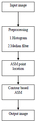
| In our project first we have to read the inpuut image and then input image is in under the process of preprocessing. Preprocessing contains 2 steps, one is histogram and another one is median filter. Histogram result gives enhanced image output and median filter result gives noise free image output. After finishing preprocessing process we have to mark points in the image for cephalometric analysis. Finally,Contour based ASM approach is performed in the image. | ||||||||
| First we have to mark 10 points in the image. These 10 points joint together to obtain a required cephalometric analysis. 10 points descripitions are given below | ||||||||
| ? Sella : a depression on the upper surface of the sphenoid bone. | ||||||||
| ? Nasion : The point on the skull where the nasal and frontal bones. | ||||||||
| ? Porion : The central point on the upper margin of the external auditory meatus. | ||||||||
| ? Orbitale : The lowest point on the inferior edge of the orbit. | ||||||||
| ? ANS : Automatic Nervous System. The part of the nervous system that supplies nerve endings in the blood vessels. | ||||||||
| ? PNS : Peripheral Nervous System. Nerves that are outside of the brain and spinal cord. | ||||||||
| ? Pogonion : The anterior midpoint of the chin. | ||||||||
| ? Gnathion : The most outward and everted point on the profile curvarture of the chin. | ||||||||
| ? Menton : The most inferior point on the chin in the lateral view of cephalogram landmark. | ||||||||
| ? Gonion : The most inferior,posterior,and lateral point on the external angle of the mandible. | ||||||||
INPUT IMAGE |
||||||||
| This is a cephalogram image that is an X-ray of the craniofacial area. A cephalometric analysis could be used as means for measuring growth in children. An X-ray image of structures of head. It can also mean a radiograph of the head,including the mandible,in full lateral view,that is used for making cranifacial measurement. Craniofacial is a medical term that relates to the bones of the skull and face. | ||||||||
| Ater read the input image,then we provide preprocessing method for image enhancement as well as for removing noise in an image. | ||||||||
PREPROCESSING |
||||||||
| Preprocessing method contains two process. They are, | ||||||||
| 1.Histogram | ||||||||
| 2.Median filterr | ||||||||
| Then the histogram and median filter techniques are described below to enhance and to remove noise in an image. | ||||||||
HISTOGRAM |
||||||||
| Histogram method is used to enhance the edge of the image. It is used to improve the visual quality of the image.The histogram of an image is a plot of the number of occurrances of gray levels in the image against the gray level values. It enhances the contrast of images by transforming the values in an intensity image, or the values in the colormap of an indexed image. So that the histogram of the output image approximately matches a specified histogram. This image gives the enhanced image result. Edges are very clear and easy to analyse. Edges are significant local changes of intensity in an image. In this image edges are the boundaries between segments.The histogram graph that shows the probability distribution of gray levels. | ||||||||
| After finishing the image enhancement using histogram method then we provide the process to removing the noise in the image. For this processes of noise removing we used median filter technique. | ||||||||
MEDIAN FILTER |
||||||||
| It is used to remove the noise in the image. And also preserve the sharpness of image edges while removing noise. Median filter is used to smoothing the image. | ||||||||
| The median is calculated by first sorting all the pixel values from the surroundings neighbourhood into numerical order and then replacing the pixel being considereed with the middle pixel value. | ||||||||
| After finishing the preprocessing method then we tranferring the image for ASM point location process. | ||||||||
ASM POINT LOCATION |
||||||||
| First we have to mark all the points(10) in the image(1 image 10 points).By using low pass interpolation we have to generate more points in between that 10 points. Interpolation is the process of determining the values of a function at positions lying between its samples. This permits input values to be evaluated at arbitary positions in the input. | ||||||||
| Interpolation reduces the bandwidth of a signal by applying low pass filter to the discrete signal. It reconstructs the signal lost in the sampling process and also with an interpolation function it smoothing the data samples. It is a best way in which images are enlarged. It also gives the best quality or visible distinction for each pixel in an image,is extracted throughout the enlargement process. Finally,interpolation is defined to be the estimation of the value of unknown points by using the values of known points. | ||||||||
CONTOUR BASED ASM |
||||||||
| Images and graphics plays an important role in the design as well as in the manufacturing. Cephalograms image provides guidance on optimal design in terms of location, preparation and the shape and configuration of sub components.The graphical representation through a direct manipulation provides natural design environment. The ASM function needs a training set of points to segment the cephalograms images. | ||||||||
| The training set of ASM function yields a shape vector. For the shape vectors we have to find the eigen-values and eigenvectors. The deformation of the mean shape is represented by the eigen-vectors and the eigen-vectors with the large value is accounted for the major changes in shape which is seen over the training set. | ||||||||
| To represent most of the variation seen in the training set which is typically much smaller than the number of points in the shape vector, the number of modes are required. A very compact representation of the deformations have been extracted which is seen in teeth shapes. We have to restrict our deformations to within 3 standard deviations of the mean shapes are given below: | ||||||||
| ? For a better position of the point we have to suggested shape by looking in the image. This can be done commonly which is referred to as ‘profile model’ which is looking forward to match the model template. | ||||||||
| ? Then finally we have to confirm the suggested shape to the point distribution model which is commonly referred to as a “shape model”. | ||||||||
| This type of Active Shape Model technique is widely used to analyse images of faces, mechanical assemblies and medical images (in 2D and 3D). This type of ASM model is closely related to the Active Appearance Model (AAM). This active appearance model is also known as a “Smart Snakes” method, since this method is an analog to an Active Contour model which respect explicit shape constraints. | ||||||||
| This ASM model is trained manually from drawn contours in training images. Using Principal component analysis (PCA), this ASM model finds the main variations in the training data set. This enables the model to automatically recognize whether the contour is possible or good object contour. | ||||||||
| This ASM model modes also contains matrices which describes the texture of the lines perpendicular to the control point, and in each step these are used to correct the positions. An initial contour is deformed by the foundation of best texture match after creating the ASM model for the points. This process is called an iterative process because the movement of control point is limited by which the ASM model is recognized from the training data as a normal object contour. | ||||||||
| Contour lines are nothing but straight or curved lines on a map which describes the intersection of real or hypothetical surface with one or more horizontal planes. A training set of hand annotated images are required for the ASM model. This annotation took the form of a set of points joined with the line segments, and gives an outline of the major structures in an image. | ||||||||
| In addition to the ASM model Active Appearance Model is defined. This AAM approach uses a gray-level model of the entire images which is used to drive the template matching and it should search more for the robust. The Active Shape Model represents another model which is a deformable model where a ststistical model of the global shape variation is built from a training set. This model is also referred to as the “Point Distribution Model”. It is then used to fit the model to unseen occurrences of the object which is early annotated in the training set. | ||||||||
PERFORMANCE MEASURES |
||||||||
| Mean is commonly reffered to as an average. Here the use of mean is to calculate the average among various points which have been located at cephalogram image. | ||||||||
| This can be generalized by the formula below: | ||||||||
| The variance of a data set is the arithmetic average of the squared differences between the values and the mean. Here the use of variance is to find the difference among the previous methods. | ||||||||
| Thus, the variance of a frequency distribution is given by, | ||||||||
| The above plot shows that outlier percentage Vs error. The blue line indicates the error rate of previous method and the red dotted line indicates that the error rate was reduced,since we implemented ASM with contour. | ||||||||
CONCLUSION |
||||||||
| ASMs do provide sufficient accuracy for cephalometric analysis.This evaluation should provide a model for proposed studies and the image result can be used to make direct comparisons between the performance. The aims of our project is to reducing the time required to obtain an analysis,improving the accuracy of landmark identification and reducing errors due to clinician subjectivity. Hence we reduced the error rate and 98% of accuracy is achieved and is proven. Hence this work can be further extended for clinical diagnosis, case based reasoning. | ||||||||
Figures at a glance |
||||||||
|
||||||||
References |
||||||||
|


