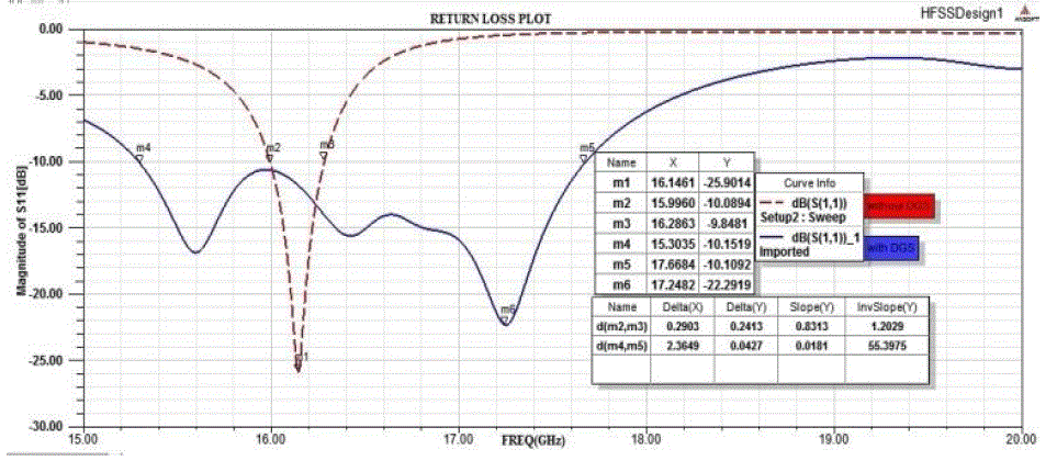
A novel compact design for bandwidth enhancement of rectangular microstrip array is presented in this paper. The basis for achieving the bandwidth enhancement is through metamaterial structure. Two types of metamaterial namely EBG and DSG are studied. Metamaterial structures are used for further antenna performance improvement, which suppress surface waves and improve the design characteristics. In this paper two cross slots cuts in the ground plane, which enhance the bandwidth of reference antenna. This shape produces bandwidth ranging from 15.30 GHz to 17.66 GHz, gives impedance bandwidth of 2.3649 GHz, whereas reference antenna without DSG is having impedance bandwidth of 290 MHz.
Keywords |
| Rectangular patch array, EBG, DGS, modified ground, Defected ground, HFSS-13. |
I. INTRODUCTION |
| In recent years, a new technology has emerged which may be the key to developing wideband microstrip
antennas. This technology manipulates the substrate in such a way that surface waves are completely forbidden from
forming, resulting in improvements in antenna efficiency and bandwidth, while reducing sidelobes and electromagnetic
interference levels. These substrates contain so called Photonic Crystals. Also known as electromagnetic band-gap
(EBG) structures and electromagnetic band-gap materials (EBMs), are a class of periodic metallic, dielectric, or
composite structures that exhibit a forbidden band, or band gap, of frequencies in which waves incident at various
directions destructively interfere and thus are unable to propagate [6]. Based on the dimensional periodicity of the
crystal structure, the band gaps can be in one, two, or three-dimensional planes, with the level of complexity increasing
as the dimensions increase. EBG structure is perturbed by either removing or adding a material with a different
dielectric constant, size, or shape, a “defect” state is created in the forbidden gap, where an electromagnetic mode is
allowed, and localization of the energy occurs. However, in implementing EBG, a large area is needed to implement
the periodic patterns and it is also difficult to define the unit element of EBG [9]. Whereas the defected ground
structure (DGS) has similar microwave circuit properties as EBG. This paper focuses the effect of two element
microstrip patch antennas array on a uniform substrate with DGS structures [1],[6]. |
| In this case, the ground of microstrip antenna is defected by etching the ground plane. Recently, many shapes of
slot have been studied: circle dumbbells and concentric ring-shape [1]. Yuli Zulkifli, Susy Tri Lomorti, Eko Tjipto
Rahardjo in , “ Improved Design of Triangular Patch Linear Array Microstrip Antenna Using Isosceles Triangular -
Defected Ground Structure[1],” proposed that application of DGS are to suppress harmonic suppress cross-polarization
radiation from patch antenna , improves impedance matching and enhance bandwidth and gain . Nasimuddin, Zhi Ning
Chen, and Xianming Qing, “A Compact Circularly Polarized Cross-Shaped Slotted Microstrip Antenna [3],” proposed
cross pattern which enhance the bandwidth and gain of antenna . WeiXing Liu, YinZeng Yin, WenLong Xu, and
ShaoLi Zuo , “Compact Open-Slot Antenna With Bandwidth Enhancement, [8]” in this paper an inverted-L-shaped
open slot antenna in ground plane and a linear tapered slot antenna are presented to enhance the impedance bandwidth.
In this article array of two rectangular microstrip antenna with two slots in ground plane has been proposed. This DGS
shape can improve the antenna performance of the reference antenna .Two cross-shaped slots are cut in the ground
plane. The radiation performance of the antenna is characterized by the dimension of the DGS and by locating the DGS at specific position has been optimized to give wide bandwidth. This slot shape DGS is added to obtain EBG
effect. This will be proven by simulation of array using simulation software HFSS-13. |
II. DESIGN OF ANTENNA ARRAY |
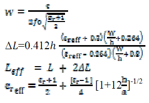
| The array of antenna is shown in Figure 1. The array consists of two rectangular patch array and fed by micro
stripline. The following classical equations are used to designed array [2], [5]. |
 |
| The dimension of ground plane is 12.91mm × 27.55mm. To fabricate the antenna, Roger RT/ duroid 5880 (tm) is
used. The dielectric material has thickness ‘h’ of .254 mm with εr = 2.2 and tangential loss of .0009. The microstrip
patch antenna include the length as 7.3 mm and width as 6 mm .The rectangular patches are separated by a distance of
14.52mm , The network is designed to realize impedance matching by using quarter wavelength impedance
transformers [3]. The network has a center line of 100 which is fed at its center by a 50Ω transmission line. The
impedance is transformed to 50Ω through a 70:7 quarter wavelength line as shown in Figure 1 (a) . Figure 1 (b) shows
the dimension and position of slots, which is optimized to give wideband are separated by 5.452mm with length as 8.8
mm and width as .2mm in cross pattern. |
III. SIMULATION AND RESULT |
| This section outlines the result of array using HFSS-13 and analyzes the 1×2 array with and without defected
ground structures. Figure 2 shows simulation result of return loss, both of antenna design with and without defected
slots in ground (DGS). |
| Antenna without DGS resonant at frequency of 16.14 GHz with return loss of -25.9 dB and have the bandwidth
of 290 MHz. Whereas for antenna with DGS resonates at 15.60 GHz and 17.24 GHz with return loss of -16.82 dB and
-22.29 dB respectively. As the slots in the ground improve the performance characteristics as it suppress the harmonics
and enhance the bandwidth of antenna. The antenna with DSG is having impedance bandwidth of 2.3649 GHz which is
2.70 GHz more than of reference antenna. |
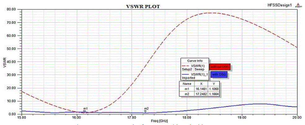
| Another important performance parameter of antenna is VSWR. For a lossless antenna its value is equal to 1, but
due to ohmic losses, mismatch losses, mutual coupling effects among patches degrade the antenna performance. From
Figure 3 its shows that’s VSWR is better for defected ground antenna for a wide range of frequency and best value is
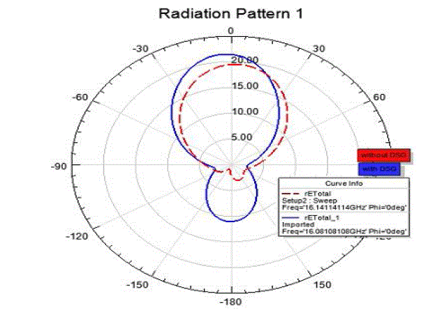
1.15 whereas reference antenna is having less range with minimum of 1.10. Figure 4 shows the radiation pattern of
antenna, due to cross slots structure in the antenna the power is radiated towards the lower side also, but improved for
DGS. |
IV. CONCLUSION |
| In this rectangular array with cross slots in ground plane was simulated and the obtained performance was
evaluated. The use of metamaterial structure periodical cross slots were introduced and analyzed. It is shown that, the
microstrip antenna bandwidth performance was improved by using cross slots. This shape produces bandwidth ranging
from 15.30 GHz to 17.66 GHz, gives impedance bandwidth of 2.3649 GHz, whereas reference antenna without DSG is
having impedance bandwidth of 290 GHz. |
| The design can be improved with different basic parameters such as type of substrate, dielectric constant, the
thickness of the substrate and different type of feeding methods. Design different EBG structures to make comparison.
From this work, we can also design the EBG structure for different operating frequency and even for multiband
frequency. |
Figures at a glance |
 |
 |
 |
 |
| Figure 1 |
Figure 2 |
Figure 3 |
Figure 4 |
|
| |
References |
- Fitri Yuli Zulkifli, Susy Tri Lomorti, Eko Tjipto Rahardjo, “Improved Design of Triangular Patch Linear Array Microstrip Antenna UsingIsosceles Triangular - Defected Ground Structure,” in Proceedings of Asia-Pacific Microwave Conference 2007
- Lal Mohan Bhowmik ,Craig Armiento , Alkim Akyurtlu ,William Miniscalco , Jagannath Chirravuri ,and Christophe McCarroll, “Design andAnalysis of Conformal Ku-Band, Microstrip Patch Antenna Arrays,” in IEEE,2013, pp. 815-820.
- Nasimuddin, Zhi Ning Chen, and Xianming Qing, “A Compact Circularly Polarized Cross-Shaped Slotted Microstrip Antenna,” in IEEETRANSACTIONS ON ANTENNAS AND PROPAGATION, VOL. 60, NO. 3, MARCH 2012 , 0018-926
- Pirhadi and M. Hakkak , “USING ELECTROMAGNETIC BANDGAP SUPERSTRATE TO ENHANCE THE BANDWIDTH OF PROBEFEDMICROSTRIP ANTENNA,” in Progress In Electromagnetics Research, PIER 61, 215–230, 2006.
- Yahya S. H. Khraisat, Melad M. Olaimat, “Comparison Between Rectangular and Triangular Patch Antennas Array,” in 19th InternationalConference on Telecomm. (ICT 2012).
- D. N. Elsheakh, H. A. Elsadek, and E. A. Abdallah, “ULTRA-WIDE BANDWIDTH MICROSTRIP MONOPOLE ANTENNA BY USINGELECTROMAGNETIC BAND- GAP STRUCTURES,” in Progress In Electromagnetics Research Letters, Vol. 23, 109-118, 2011
- M. Gujral, J.L. Li t. Yuan and C.W Qui, “BANDWIDTH IMPROVEMENT OF MICROSTRIP ANTENNA ARRAY USING DUMMY EBGPATTERN ON FEEDLINE”, in Progress In Electromagnetics Research, Vol. 127, 79-92, 2012
- WeiXing Liu, YinZeng Yin, WenLong Xu, and ShaoLi Zuo ,“Compact Open-Slot Antenna With Bandwidth Enhancement,” in IEEEANTENNAS AND WIRELESS PROPAGATION LETTERS, VOL. 10, 2011
- J. P. Geng, J. J. Li, R. H. Jin, “THE DEVELOPMENT OF CURVED MICRO STRIP ANTENNA WITH DEFECTED GROUNDSTRUCTURE,” in Progress In Electromagnetics Research, PIER 98, 53-73, 2009
- Constantine A. Balanacis, “Antenna Theory, Analysis and design,” Third Edition, John Wiley & Sons,Inc.
- Ramesh Garg , Prakash Bhartia , Inder Bhael and Apisak Ittipiboon , “ Microstrip Design Antenna Handbook,”Artech House, Boston London.
- Fan Yang and Yahya Rahmat, “Electromagnetic Band Gap Structures in Antenna Engineering,” Cambridge University Press.
|