Beamforming-array signal processing is a powerful means of increasing capacity and coverage of the mobile communication networks. It supports the next generation broadband cellular system to efficiently carry populated traffic over a limited spectrum due to its co-channel interference mitigation capability. This paper presents performance comparison of three beamforming methods namely null steering, minimum variance distortionless response (MVDR) and minimum mean square error (MMSE) beamforming. It is observed that MMSE beamforming is most suitable for practical non-line-of-sight multipath environment. The work is further extended to downlink beamforming problem for multicell network which is formulated as minimization of transmitted power by all base stations (BSs) subject to SINR constraints at each mobile. The conventional per cell basis beamforming and coordinated multicell beamforming are implemented to achieve downlink transmit power optimization using downlink beamforming. Both algorithms use uplink (UL)-downlink (DL) duality concept to solve complicated DL beamforming by using dual uplink problem. Per cell basis beamforming treats intercell interferences as a part of background noise while coordinated multicell beamforming considers intercell interferences for weight vector calculation. Thus, per cell basis optimization does not lead to a joint optimal solution which is possible by coordinated multicell beamforming. The important feature of coordinated beamforming algorithm is that, it leads to distributed implementation in time division duplex (TDD) system. The distributed implementation is less complex and requires only beamforming level coordination unlike centralized implementation which requires system level coordination and thus it is more complex. Thus, in this paper per cell basis beamforming and coordinated multicell beamforming has been implemented and compared for mobile wimax multicell network. The simulation results proved that coordinated beamforming outperforms per cell basis beamforming for different values of SINR and user locations.
Keywords |
| Array signal processing, beamforming, multicell network, uplink-downlink duality. |
INTRODUCTION |
| N recent years there is an enormous rise in the traffic for mobile and personal communication systems. This is due to
dynamic business and social applications which has driven the popularity of mobile data services and created a need for
all-time connectivity at any time and anywhere. Far beyond simple voice communication, today’s wireless networks
must support applications such as internet access, video streaming etc. Thus major demands for next generation mobile
communication system are |
| 1) broadband data rates. |
| 2) high capacity to support increasing traffic load over limited spectrum. |
| 3) high quality of service in affordable prize. |
| To achieve high data rates and high capacity it is needed to reduce interferences and noise which greatly affects the
performance of cellular system, and increase the desired signal power. With limited spectrum availability, achieving
this goal is difficult due to co-channel interferences. So more advanced technologies are desperately needed to fulfill
the need of next generation wireless mobile communication. |
| Beamforming- antenna array signal processing is one of the most powerful and promising technology which reduces
co-channel interferences and noise and thereby ensures high signal to interference noise ratio (SINR). Beamforming
antenna has the ability to focus energy in direction of desired users and nulls in direction of interferences. Such
directional transmission reduces co-channel interferences and allows co-channel users to be separated by spatial
multiplexing, thereby increasing capacity of cellular network. Beamforming systems require less transmission power as
compared to omni-directional antennas. Thus it helps to reduce transmission power without degrading quality of
service. Also the directional transmission increases coverage by each base station (BS) thereby reducing capital
expenditure and operating expenditure which gives cost efficient network deployment. Thus beamforming has proved its benefits for next generation mobile cellular networks and helps mobile wireless operators to provide high speed data
services as per the demand in affordable price to subscribers by supporting large number of users over limited available
spectrum. |
| In this paper, performance evaluation has been carried out for beamforming design methods namely null steering,
minimum variance distortionless response (MVDR) and minimum mean square error (MMSE) beamforming. The work
is further extended to downlink (DL) / transmit beamforming problem for multicell network, which is of great interest
nowadays as in conventional wireless system antenna arrays are typically deployed at base station, whereas the mobile
terminals are equipped with single antennas. In this work downlink beamforming problem is formulated as
minimization of transmitted power by all base stations (BSs) subject to SINR constraints at each mobile station (MS).
Downlink (DL) / transmit beamforming is more complicated than uplink (UL) / receive beamforming as all
beamformers must be optimized jointly. Thus, complicated downlink problem is solved by dual uplink problem which
is easier to solve. The UL-DL duality concept is used to solve DL beamforming problem efficiently. |
| The conventional per cell basis beamforming algorithm and coordinated multicell beamforming algorithm are
compared to study the benefits of BS coordination in multicell network for power optimization using downlink
beamforming. The coordinated multicell beamforming algorithm considered in this paper is implemented in distributive
fashion in time-division duplex (TDD) system as it only requires beamforming level coordination and thus it is easy to
implement. |
| A. Related Work |
| The overview of beamforming technology and different beamforming methods for narrowband and broadband
signals have been investigated by L. Godara, 1997 [1]. The implementation of different beamforming algorithms is also
presented in literature [2], [3], [4]. Out of different beamforming algorithm null steering, MVDR and MMSE
beamforming is found more attractive for wireless communication systems. |
| Recently transmit/downlink beamforming problem has been proposed in many works [5]-[17]. The downlink
beamforming problem can be formulated in two ways as: |
| 1) Reduce the transmitted power by BS subject to SINR constraints at each MS. Thus in this lower limit on SINR is
fixed. For this limit transmitted power is optimized so as to reduce interference to the other users in cell and out of cell. |
| 2) Optimized SINR subject to transmit power constraint of BS. In this target transmission power of BS is fixed and
SINR at MS is optimized to achieve high throughput rate (bps/Hz) [5]-[8]. |
| For DL beamforming weight vector calculation channel state information (CSI) is required. In frequency division
duplex (FDD) system, UL and DL channels are different. Thus for DL beamforming, DL channel is estimated at MS
and is feedback to BS for weight vector calculation. Performance of DL beamforming is greatly affected due to limited
bandwidth of feedback channel. This limitation is overcome by efficient weight vector codebook design. In
Grassmannian weight vector codebook design method the correlated vectors are removed to reduce the size of
codebook [9] and codebook is made available to both BS and MS. When signal arrives at MS, it estimates the best
weight vector from predetermined codebook which matches the estimated channel. The index of this weight vector is
feedback to BS. By using this feedback, BS selects the weight vector from codebook to achieve optimum transmission.
For temporally correlated channels feedback compression algorithm is proposed to compress feedback CSI in alternate
feedback intervals [10]. |
| In time division duplex (TDD) system UL and DL channels are reciprocal and thus complicated DL transmit
problem can be solved by UL receive beamforming by using UL-DL duality concept [11]-[14], [17]. In single cell
scenario downlink power optimization is done on per cell basis which considers intercell interference as a part of
background noise [13], [14]. This single cell DL beamforming problem can also be formulated as a second order cone
programming (SOCP) problem [15]. This helps to interpret UL-DL duality via Lagrangian theory of convex
optimization [14], [16], [17]. |
| For multicell DL beamforming, coordination between different BSs in network is needed, which is achieved in
centralized or distributive manner. In centralized co-ordination scheme, the BS’s in different cells act as single BS with
distributed antennas and schedules the user by estimating weight vector corresponding to best channel out of all
available channels. At particular instant BS which has the best channel serves the user and weights are calculated for
that channel. Thus centralized coordination requires, to exchange large data among all BSs, all BSs need to have access
to data destined for MSs of other BSs and also scheduling decision will be jointly made at the BSs. This increases
feedback overhead and complexity [18]-[22]. |
| Unlike centralized beamforming which requires signal level coordination, distributive coordination requires
beamforming level coordination [17]. In distributive coordination, each BS performs beamforming for its own users by considering intercell interference for weight vector calculation. Thus there is no centralized beamforming and user
scheduling which makes system implementation much easier than centralized coordinated network. |
| B. Organization |
| The remainder of the paper is organized as follows. Section II contains beamforming design methods. Downlink
beamforming and transmission power optimization is presented in section III. Section IV gives simulation results
followed by concluding remarks in section V. |
BEAMFORMING DESIGN METHODS |
| This paper presents three methods of beamformer design namely Null steering beamforming, Minimum variance
distortionless response (MVDR) and Minimum mean square error (MMSE). Depending on system requirement one of
the methods can be selected for beamformer design. |
| A. System Model |
| A single cell with M mobile users and base station with L-element antenna array is considered. Let there be d desired
signal sources and l interference sources transmitting on same frequency channel simultaneously. Then the signal
received by antenna array becomes, |
 |
| where ai (φ) is a array steering vector denoting the amplitude gain and phase shift of the signal of ith user. j denote the
desired users and k denote interferences. si (t) is signal vector and n(t) is random noise component with zero mean and
unity variance. |
| The beamformer system output can be written as, |
 |
| where w is weight vector and superscript H denote conjugate transpose. |
| B. Null Steering Beamforming Algorithm |
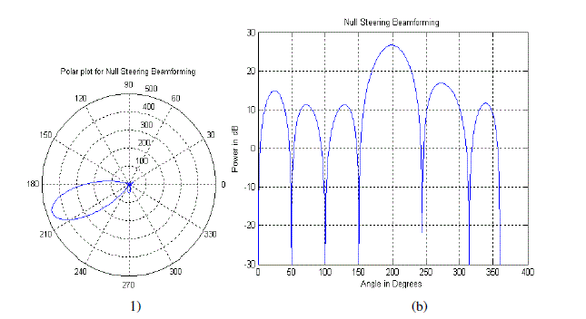
| Null-Steering Beamformer forms a beam in the desired direction and nulls in interference directions. Two modes of
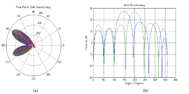
null-steering beamforming are considered, null steering beamforming for single desired user and multi-beamforming
for multiple desired users. Thus, the null-steering beamforming problem can be formulated as,
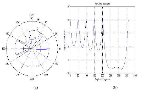
1) Estimation of Direction of Arrivals (DOAs) using DOA Algorithm: Minimum variance distortionless response
(MVDR) DOA algorithm is used for DOA estimation for which the power spectrum is given as [1], |
 |
| where R is array correlation matrix defined by R = E [x(t) xH(t)].
2) Validation Process: Once DOAs are estimated for all incoming signal, next is validation process which separates out
desired signal from interferences. If after validation process, it is found that there is only single desired user and others
are interferences then null steering mode is invoked. If it is found that there is more than one desired user then multibeamforming
mode is invoked. |
| 3) Null Steering Beamforming: The open loop null steering algorithm has developed to satisfy following constraints
[23], [24]: |
| where ad array steering vector for a desired user and al array steering vector for a interferences. |
| An optimal weight for a null steering array is given as [23], |
 |
| where IL is L×L identity matrix. |
| 4) Multi-Beamforming: During signal validation process, if it is observed that there are more than one desired user
then multibeam mode is triggered. The weight vectors for all desired users are calculated by using (4). In this mode,
due to the presence of multiple desired users the time window is defined for each user. Certain percentage of duty cycle
is allocated to each user such that for the assigned time period beam is formed towards that user [3]. Thus for certain
percentage of time duration one user is served and for next interval the other user is served. |
| C. Minimum Variance Distortionless Response (MVDR) Beamforming Algorithm |
| The MVDR beamformer does not require the knowledge of the directions of the interferences for weight vector
calculation. It requires only the direction of the desired signal. |
| MVDR weight vector is given as [25], [26] |
 |
| These weights are the solution of the following optimization problem: |
 |
| Thus, the beamformer weights are selected by minimizing the mean output power while maintaining unity response
in the look direction. The constraint ensures that the signal passes through the beamformer undistorted. Therefore, the
output signal power is the same as the look-direction source power. The minimization process then minimizes the total
noise, including interferences and uncorrelated noise. Minimization of total output noise, while keeping the output
signal constant is same as maximizing the output SINR. As MVDR beamformer maximize SINR only in one direction,
this beamformer is not suitable for non-line-of-sight (NLOS) multipath environment where desired signal get scatter in
many directions. Thus it can be implemented for rural environment where multipath signals do not exist. |
| D. Minimum Mean Square Error (MMSE) Beamforming Algorithm |
| In multipath fading environment, MMSE beamformer gives the optimum result. This beamformer utilizes reference
signal which is correlated to desired signal and uncorrelated with interferences. In MMSE algorithm the array output is
compared with reference signal, thus weight vectors are calculated such that beams are produced in the direction of
multipath signal those matches with reference signal unlike MVDR. Thus, the MMSE beamforming is optimum
candidate for NLOS urban environment, as it not only reduces the interference but also multipath fading is mitigated.
In MMSE beamforming array output is subtracted from an available reference signal r(t) to generate an error signal
ε(t) = r(t) – wHx(t), which is used to control the weights. Weights are adjusted such that the mean square error between
the array output and the reference signal is minimized. The optimal weight vector is given by Wiener–Hoff equation
[25], [26] |
 |
 |
| where z is the cross-correlation between the reference signal r(t) and the signal vector x(t). |
DOWNLINK BEAMFORMING AND TRANSMISSION POWER OPTIMIZATION |
| In conventional wireless system, antenna arrays are typically deployed at base station, whereas the mobile terminals
are equipped with single antennas. Thus, beamforming has to be performed in downlink to achieve desired performance. |
| Downlink beamforming is more complicated than uplink as in DL all beamformers must be optimized jointly. Due to
nonorthogonal transmission in cell, the specific choice of one of the user’s beamformer may affect the crosstalk
experienced by other users. Hence, the SINR values of all users are coupled, which makes downlink beamforming a
complicated task. The uplink beamforming is achieved independently at each BS while in downlink beamforming BS
has to consider SINR at the all MSs to optimize the beamformer output. As a result, downlink beamforming has to be
done jointly in the entire network. |
| In this paper downlink beamforming problem is formulated for minimization of transmitted power across all BS
subject to SINR constraints at each mobile receiver. This paper presents per cell basis optimization and coordinated
multicell optimization algorithm for downlink beamforming of multicell wireless network. |
| A. Problem Formulation |
| 1) System Model: This paper considers a multicell multi-user spatial multiplex system with N cells and K users per
cell, with Nt antennas at each base-station and a single antenna at each remote user. Multiuser downlink transmit
beamforming is employed at each base-station. Let xi,j be a complex scalar denoting the information signal for the jth
user in the ith cell, and wi,j Є CN
t
x1 be its associated beamforming vector. The received signal at the jth remote user in the
ith cell, denoted as yi,j, is a summation of the intended signal, intracell interference, and intercell interference: |
 |
| where hl,i,j Є CN
t
x1 is the vector channel from the base station of the lth cell to the jth user in the ith cell, and ni,j is the
additive white circularly symmetric gaussian complex noise. |
| Transmit Beamforming Problem: Let wi,j be the beamforming vectors, then the SINR Γi,j for the jth user in the ith cell
can be expressed as [17] |
 |
| Let γi,j be the SINR target for the jth user in ith cell. A total transmit power minimization problem subject to SINR
constraints can then formulate as follows: |
 |
| where αi is the power constraint of each BS and the minimization is over the wi,j’s. |
| In conventional per cell basis optimization, multicell beamforming problem is solved by considering out-of-cell
interference as a part of background noise and beamformers of all out of cell mobile stations (MSs) are fixed. For
calculation of beamforming weights conventional beamformer only considers the interference of users in same cell and
optimizes transmitted power. It does not consider intercell interference for calculation of weight vector. Thus, per-cell
basis optimization does not necessarily lead to a joint optimal solution. Significant performance improvement may be
obtained if base-stations coordinate in jointly optimizing all of their beamformers at the same time.
Joint optimal solution i.e. coordinated beamforming for multicell in which each BS calculates the weight vector for
each user by considering channel and power of the other users in its own cell as well as the neighboring cell. Such
coordination helps to mitigate interference in the scenario when two users belonging to two different cells are present
along the same direction and are at cell edge. In such situation the two base station schedules the users such that beam
for both users are not formed simultaneously [27]. For such coordination channel state information is required to
exchange between two base stations. If users are not at cell edge but both are at same spatial location coordinated
beamforming is done reduced the transmitted power subject to SINR at each user. |
| B. Conventional Per Cell Basis Beamforming |
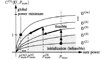
| To solve the downlink beamforming problem with per cell basis optimization, power minimization algorithm for
single cell which has proposed by Martin Schubert and Holger Boche [13] has been extended for multicell network. It
can be proved that the SINR at each user is inversely proportional to cross-talk between the users. The optimal
beamforming weights are calculated to reduce cross-talk between the users and to achieve feasible SINR region (i.e.
SINR ≥ γ) and once it is achieved transmission power is minimized. An illustration of the algorithm is given in fig. (1). |
| Let there be K users per cell in multicell network. The beamforming is performed on per cell basis. The
beamforming weight vectors ui are collected in a matrix U = [u1,…….., uK]. The downlink transmission power vectors pi
are stack in a vector p = [p1,…….., pK ]T and the total transmission power per cell is given by || p ||1. The uplink transmit
powers of all mobiles are stacked in a vector q = [q1,…….., qK ]T. The total transmission power per cell of both uplink and
downlink is limited by Pmax i.e. maximum allotted transmission power per cell for considered cellular network.
The downlink spatial covariance matrices are given by, |
 |
| |
 |
| |
 |
| |
 |
| |
 |
 |
| |
 |
| |
 |
| |
 |
| |
 |
| |
 |
| |
 |
| |
| |
| |
| |
| |
| |
| |
| |
| |
| |
| |
| |
| |
| |
| |
Tables at a glance |
 |
 |
| Table 1 |
Table 2 |
|
| |
Figures at a glance |
 |
 |
 |
 |
| Figure 1 |
Figure 2 |
Figure 3 |
Figure 4 |
 |
 |
 |
 |
| Figure 5 |
Figure 6 |
Figure 7 |
Figure 8 |
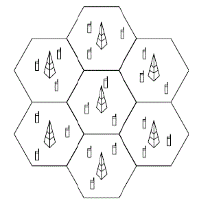 |
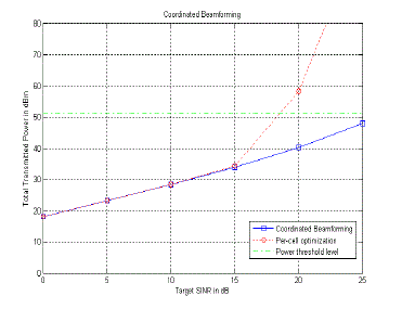 |
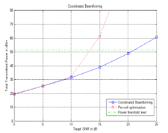 |
| Figure 9 |
Figure 10 |
Figure 11 |
|
| |
References |
- Alipio BC, David FC, Isabel RS, Juan CNM. Manuel AE. Comparison of batch, stirred flow chamber, and column experiments to study adsorption, Desorption and transport of carbofuran within two acidic soils. Chemosphere. 2012; 88(1): 106-120.
- Arnaud B, Richard C, Michel S. A comparison of five pesticides adsorption and Desorption processes in thirteen contrasting field soils. Chemosphere. 2005; 61(5): 668-676.
- Chunxian W, Jin-Jun W, Su-Zhi Z, Zhong-Ming Z. Adsorption and Desorption of Methiopyrsulfuron in Soils. Pedosphere. 2011; 21(3): 380-388.
- Chunxian W, Suzhi Z, Guo N, Zhongming Z, Jinjun W. Adsorption and Desorption of herbicide monosulfuron-ester in Chinese soils. J Environ Sci. 2011; 23(9): 1524-1532.
- Christine MFB, Josette MF. Adsorption-desorption and leaching of phenylurea herbicides on soils. Talanta. 1996; 43(10): 1793-1802.
|