International Journal of Advanced Research in Electrical, Electronics and Instrumentation Engineering
ISSN ONLINE(2278-8875) PRINT (2320-3765)
ISSN ONLINE(2278-8875) PRINT (2320-3765)
Er. Sandeep Pal Singh1, Er. Divya Gupta2
|
| Related article at Pubmed, Scholar Google |
Visit for more related articles at International Journal of Advanced Research in Electrical, Electronics and Instrumentation Engineering
Punjab State is trying to unbundle itself through privatization. Following this path the Punjab State Electricity Board is now divided into PSTCL and PSPCL. In this paper, study of transfer capability of this state is discussed to some extent. Mostly all towns and cities of the state are covered. Many cases of outages are also given. Consequently what would be the effect of these outages on transfer capability is provided in this paper. It will be very helpful for the researchers to study the scenario of the state because it is a very new concept introduced.
Keywords |
||||||||||||||||
| Punjab, PSTCL, PSPCL, PSEB | ||||||||||||||||
INTRODUCTION |
||||||||||||||||
| Punjab state Electricity Board is an utility for public sector for the essential services because power supply is the basic need of eachsand every household. Electricity is the prime requirement for the each and every work like domestic, aggriculture and commercial etc. The growth of the every state primarily depends on power system. To ensure the availability of an efficient and reliable power supply system, the public would be aware about the various activitiesperformed by the PSEB. Punjab State Electricity Board (PSEB) is Divided into two Corporations named as Punjab State Transmission Corporation Limited (PSTCL) and Punjab State Power Corporation Limited (PSPCL). PSPCL deals with the generation system i.e. from may be hydro or thermal power plant etc in Punjab state. PSTCL deals with the transmission system and distribution systemin Punjab state. The errection of transmission lines and increasing the transferring capability of transmission lines etc are handled by the PSTCL. PSTCL which came into being on 16/04/2012 is entrusted with the construction of Transmission Works in the State of Punjab. Seven numbers of 66KV Grid Sub Stations namely Ikolaha, Passiana, Gaunsgarh, BassiPathana, Udhoke, Kakrala and Dhaanaula have been upgraded to 220KV by the PSTCL, during the year 2012-2013.132KV Sub StationsTalwandiBhai has also be upgraded to 220KV. The transferring capacity increased in Punjab state grid by erecting transmission lines and expenditure incurred during the year 2010 to 2013. The total transferring capacity of PSTCL as on 31.03.2010 was 15660 MW. The capacity has been increased to 23261 MW as on 31.03.2013. Thus the capacity has been increased by 48.5% in the three years. This will make the Punjab Grid to be very stable,robustic and also reduce the losses. | ||||||||||||||||
| Capability of transferring electric power or in other words transfer capability refers to the amount of electric power that can be passed through a transmission network from one place to another place. Transfer Capability is alsothe measure of ability of the interconnected electric systems to reliably fed power from one area to another over the transmission lines (or paths) between those areas under specified system conditions.The available transfer capability of Punjab state is discussed with contingencies in case study. The transfer capability is an indicator for the security system [1]. The transfer capability is calculated for security of power system. The contingency analysis is analysed by the Punjab state grid by open circuiting the lines. The Interconnected Transformer loading on different lines is calculated with the help of contingencies. For example:- The contingency N-1 means that the one line during the transmission is to be kept open. This line may be open due to overloading on transmismission line by the relaying action[8].s Due to this, the other remaning lines are overloaded. The available transfer capability should be in the prescribed limits. If these faults occurs on other lines continuously, then the system may be collapse. | ||||||||||||||||
| This is reffered to the system blackout[2]-[3]. The transfer capability is very useful for several purposes. The lesser increase in transfer capability might be more beneficial for reliability and economic efficiency.The section II gives the background of transfer capability, section III shows the scope of transfer capability. The section IV carries the case study of utility system of Punjab and section V gives the conclusion. | ||||||||||||||||
BACKGROUND OF TRANSFER CAPABILITY |
||||||||||||||||
| The available transfer capability (ATC) is the measure of the transfer capability remaining in the physical transmission network for further commercial activity over and above previously committed uses. Mathematically, ATC is defined as the Total Transfer Capability (TTC) less than Transmission Reliability Margin (TRM) and the Capacity Benefit Margin (CBM) [6]. | ||||||||||||||||
| ATC = TTC – TRM – CBM | ||||||||||||||||
| Total transfer capability (TTC) is defined as the amount of electric power that can be transferred over the interconnected transmission network in areliable manner while meeting all of a specific set of definedpreand postcontingency system conditions. Transmission Reliability Margin (TRM) is defined as that amount of transmission transfer capability necessary to ensure that interconnected transmissionnetwork is secure under a reasonable range of uncertainties insystemconditions. | ||||||||||||||||
| Capacity Benefit Margin (CBM) is defined as that amount of transmission transfer capability reserved by load serving entities to ensure access to generation from interconnected systems to meet generation reliability requirements. | ||||||||||||||||
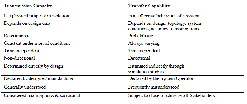
| Difference between Transfer Capability and Transmission Capacity | ||||||||||||||||
| ‘Transfer Capability’ is the measure of the ability of interconnected electric systems to reliably move power from one area toanother over all transmission lines (or paths) between those areas under specified system conditions. Transfer Capability may be limited by the physical and electrical characteristics of the systems. The limiting condition on some portions of the transmission network can shift among thermal, voltage and stability limits as the network operating conditions change over time. [8]. The distinguishing features of transmission capacity and transfer capability are tabulated below: | ||||||||||||||||
 |
||||||||||||||||
SCOPE OF TRANSFER CAPABILITY |
||||||||||||||||
| The transfer capability is very useful for many reasons. The system having large inter area transfers is more reliable, roboust and flexible than the system having the inter area transfers upto a limited extent. The transfer capability may be used as the rough indicator for the system security. For comraring the relative advantages of planned transmission improvements, the transfer capability is useful. The energy markets facilitate with transfer capability computations byproviding a quantitative basis for accessing transmission reservations. For increasing the reliability and economic efficiency, a transmission expansion is more beneficial by increasing transfer capability between the two areas of the grid. | ||||||||||||||||
| We can explain transfer capability from beginning to end with the purpose of transmission capacity by discussing the different definations and meanings of different componentsof transfer capability and explaining the different methods for calculating each component. Some assumptions are made during the transfer capability calculations and determination which may greatly influence the answer. Choices made in modeling the power system, the base case, the transfer itslf and the limiting casemust all be chosen. They can be described in following ways. The base case or halting case of afunction is the problem that we know the answer to, that can be solved without any more recursive calls. The base case is what stops the recursion from containing on forever. Every recursive function must have at least one base case (many functions having more than one).if it doesn’t. your function will not work correctlt most of the time and will most likely cause yiour program to srash in many situations, definitely not a desired effects. | ||||||||||||||||
| The transfer limited case can be determined at which the transfer is to be increased at such extent that there is a binding security limit. This limit of binding security may be a limit on the line flow, voltage collapse, voltage magnitude etc. By transferring power in the same direction would cause the violation of binding limit by compromising system security [4] - [5]. | ||||||||||||||||
CASE STUDY OF UTILITY SYSTEM OF PUNJAB |
||||||||||||||||
| In a competitive electricity market, there will be many market players such as generating companies (GENCOs), transmission companies (TRANSCOs), distribution companies (DISCOs), and system operator (SO). Similarly PunjabState Electricity Board (PSEB) is divided into Punjab State Transmission Corporation Limited (PSTCL) and Punjab State Power Corporation Limited (PSPCL). All are operating as independent companies under the government of Punjab.The available transfer capability of Punjab is shown below:- | ||||||||||||||||
| PUNJAB IMPORT CAPABILITY: | ||||||||||||||||
 |
||||||||||||||||
| Study Report is as below:- | ||||||||||||||||
| (1) Load Generation Balance: | ||||||||||||||||
| Load + Losses = Generation + Import | ||||||||||||||||
| (2) Load Power Factor: | ||||||||||||||||
| Without Capacitor = .90 | ||||||||||||||||
| With Capacitor = .99 | ||||||||||||||||
| (3) MVAR Detail: | ||||||||||||||||
| Amritsar & Jalandhar = 1555 MVAR | ||||||||||||||||
| Moga&Malerkotla= 1450 MVAR | ||||||||||||||||
| Patiala = 700 MVAR | ||||||||||||||||
| Ludhiana = 400 MVAR | ||||||||||||||||
| Total = 4105 MVAR | ||||||||||||||||
| (4) Location of Bus Split: | ||||||||||||||||
| At 220KV Mohali 1st Bus: 220KV Nalagarh - Mohali Circuit1 & 2 | ||||||||||||||||
| 220KV Rajpura Circuit1 & 2 | ||||||||||||||||
| 220KV Lalru | ||||||||||||||||
| 220KV Mohali-II | ||||||||||||||||
| 2nd Bus: 220KV Mohali-Ganguwal | ||||||||||||||||
| 220KV Mohali-RTP | ||||||||||||||||
| 220KV Mohali-Kharar | ||||||||||||||||
| 220/66KV Power TransformerNo. 1, 2 & 3 | ||||||||||||||||
| At 220KV Ablowal 1st Bus: 220KV Gobindgarh Circuit1 & 2 | ||||||||||||||||
| 220/66KV Power TransformerNo. 1 | ||||||||||||||||
| 220KV Passiana/Rajla | ||||||||||||||||
| 2nd Bus: 220KV PhagganMajra (PG) Circuit1 & 2 | ||||||||||||||||
| 220KV Patran | ||||||||||||||||
| 220/66KV Power Transformer No. 2 | ||||||||||||||||
| (5) Lines Kept Open: | ||||||||||||||||
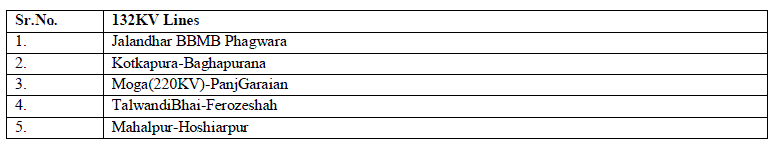
| The lines which are kept open during the study are given as under. These lines are kept open in summer season. If these lines are not kept open during the summer season, then ICTs of the lines are overloaded. So, to overcome this overloading, these lines are kept open during the summer season. When these lines are kept open during summer, then the ATC will be disturbed. Because its level becomes lower than 5000MW. For safe operation, the ATC should be near the 5300 MW. In winter, there is no need to keep these lines open. | ||||||||||||||||
| (6) N-1 Contingency of 400/220KV Transformerswithin Punjab: | ||||||||||||||||
| The readings under the normal condition is given in the table - I. At this condition, all the lines are considered in circuit. No line is to be kept open during the analysis of Table – I. The band of voltages for the 400KV bus voltage is between the 380KV to 420KV. The meaning of the equation (2*315+500 MVA) of ICT rated capacity of Patiala is that two transformers are of rated capacity of 315 MVA and one transformer is of rated capacity of 500 MVA. The total ICT rated capacity of Patiala is 1130 MVA. | ||||||||||||||||
| The N-1 contingency means the one line is kept open during the study. During the study, the line of Amritsar ICT-1on base case is kept open.The ICT loading of one line of Amritsar is zero. The sub-stations of Malerkotla and Moga are at the alarming situation and the sub-station of Patiala is near the alarming situation. When the line of Amritsar ICT-I is kept open, the readings under this condition is given in the table – II. Here, the ICT loading on one line of Amritsar increases after the line kept open. In normal case, the ICT loading is 213 MW on Each line. But the ICT loading is 319 MW on single line when the one line is kept open & ICT loading on second line is zero.During the study, the line of Amritsar-Jalandhar circuit on base case is kept open. The ICT loading of both lines of Amritsar is zero. The sub-stations of Malerkotla and Moga are at the alarming situation and the sub-station of Patiala is near the alarming situation. When the line of Amritsar-Jalandhar circuit is kept open, the readings under this condition are given in table – III.During the study, the line of Moga ICT on base case is kept open. The ICT loading of the line of Moga ICT is zero. The sub-stations of Malerkotla and Moga are at the alarming situation and the sub-station of Patiala is near the alarming situation. When the line of Moga ICT is kept open, the readings under this condition are given in the table – IV.Here, the ICT loading on one line of Moga increases after the line kept open. In normal case, the ICT loading is 194 MW on three lines & 245 MW on other line. But the ICT loading is 256 MW on three lines when the one line is kept open & ICT loading on fourth line is zero. | ||||||||||||||||
| During the study, the line of Jalandhar ICT-1on base case is kept open. The ICT loading of one line of Jalandhar is zero. The sub-stations of Malerkotla and Moga are at the alarming situation and the sub-station of Patiala is near the alarming situation. When the line of Jalandhar ICT-I is kept open, the readings under this condition is given in the table – V.Here, the ICT loading on one line of Jalandhar increases after the line kept open. In normal case, the ICT loading is 179 MW on Each line. But the ICT loading is 245 MW on single line when the one line is kept open & ICT loading on second line is zero. | ||||||||||||||||
| During the study, the line of Patiala ICTon base case is kept open. The ICT loading of the line of Patiala is zero. The sub-stations of Malerkotla and Moga are at the alarming situation and the sub-station of Patiala is near the alarming situation. When the line of Patiala ICTis kept open, the readings under this condition are given in the table – VI.Here, the ICT loading on one line of Patiala increases after the line kept open. In normal case, the ICT loading is 211 MW on two lines & 331 MW on other line. But the ICT loading is 328 MW on two lines when the one line is kept open & ICT loading on third line is zero.During the study, the line of MalerkotlaICTon base case is kept open. The ICT loading of line of Malerkotla is zero. The sub-stations of Malerkotla and Moga are at the alarming situation and the sub-station of Patiala is near the alarming situation. When the line of MalerkotlaICTis kept open, the readings under this condition are given in the table – VII.Here, the ICT loading on one line of Malerkotla increases after the line kept open. In normal case, the ICT loading is 174 MW on two lines& 274 MW on other line. But ICT loading is 256 MW on two lines when the one line is kept open & ICT loading on third line is zero. | ||||||||||||||||
| During the study, the line of Ludhiana ICT-1on base case is kept open. The ICT loading of one line of Ludhiana is zero. The sub-stations of Malerkotla and Moga are at the alarming situation and the sub-station of Patiala is near the alarming situation. When the line of Ludhiana ICT-I is kept open, the readings under this condition is given in the table – VIII.Here, the ICT loading on one line of Ludhiana increases after the line kept open. In normal case, the ICT loading is 198 MW on three lines. But the ICT loading is 249 MW on two lines when the one line is kept open & ICT loading on third line is zero. | ||||||||||||||||
| Observation: | ||||||||||||||||
| Punjab import capability (TTC) is assessed to be 5600 MW | ||||||||||||||||
| Limiting constraints is N-1 contingency of following:- | ||||||||||||||||
| Tripping of 400/220KV, 315 MVA ICT at Moga (overload other three ICTs) | ||||||||||||||||
| Tripping of 400/220KV, 500 MVA ICT at Patiala (overload other two ICTs) | ||||||||||||||||
 |
||||||||||||||||
 |
||||||||||||||||
CONCLUSION |
||||||||||||||||
| `The transfer capability is calculated for security of the power system. The contingency analysis is analysed by the Punjab state grid by open circuiting the lines of interconnected transformers. If these lines are not kept open during the summer season, then ICTs of the lines are overloaded. So, to overcome this overloading, these lines are kept open during the summer season. Because its level becomes lower than 5000MW. For safe operation, the ATC should be near the 5300 MW. In winter, there is no need to keep these lines open. Here the interconnected transformers are used so that in case of any fault on a single line may not interrupt the system, the load can be share by the other lines. This make the system more reliable and roboust. | ||||||||||||||||
ACKNOWLEDGEMENT |
||||||||||||||||
| The authors would like to thank the Senior Executive Engineer in SLDC (Operation) Er. AkshayGarg and other staff members of State Load Dispatch Centre for providing facilities to carry out this work. The authors would also like to thank the HOD of Electrical Engineering Department in BBSBEC, Fatehgarh Sahib, S. Gursewak Singh Brar forproviding facilities to carry out this work. | ||||||||||||||||
Tables at a glance |
||||||||||||||||
|
||||||||||||||||
References |
||||||||||||||||
|