International Journal of Advanced Research in Electrical, Electronics and Instrumentation Engineering
ISSN ONLINE(2278-8875) PRINT (2320-3765)
ISSN ONLINE(2278-8875) PRINT (2320-3765)
Preethi M.P1, Dr.K.Sebasthirani2
|
| Related article at Pubmed, Scholar Google |
Visit for more related articles at International Journal of Advanced Research in Electrical, Electronics and Instrumentation Engineering
The power extracted from renewable energy resources has some limitations that are occurred due to the weather changes and scarcity of sources. The power demand and scarcity can be minimized by improving the power extracting methods. Multilevel inverter requires several number of dc sources for synthesizing the ac output voltage waveform. Therefore a new method of multilevel inverter with reduced number of switches has been designed that uses hybrid modulation technique where it is the combination of Fundamental Frequency Pulse Width Modulation (FPWM) and Multi Sinusoidal Pulse Width Modulation MSPWM for each inverter cell operation that is processed by sequential switching pulse which reduces the power loss and conduction loss. This proposed designed with reduced number of switches, the conduction and switching losses gets decreased, which leads to increase the efficiency of the inverter. The size and power consumption in the driving circuits can also be minimized. This structure minimizes the Total Harmonic Distortion (THD) of the output voltage waveforms.
Keywords |
||||||||||
| Cascaded H-bridge inverter,Fourier analysis, Hybrid Modulation, Multilevel Inverter,MATLAB, THD. | ||||||||||
INTRODUCTION |
||||||||||
| Nowadays Multilevel inverters are used as a new kind of power converter circuits, it can be classified into three main topologies as diode-clamped, flying capacitor and cascaded H bridge multilevel inverters. The dc-link capacitor voltages can be balanced in the absence of any added circuits or individual dc voltage sources. Real and reactive power conversion applications are also uses this approach [1]. Neutral point regulation is provided for the three level diode clamped multilevel inverter that contains a multiple carrier modulator combined along with it [2]. Comparison of diode-clamped and cascaded multilevel converter combined with energy storage systems [3]. Individual capacitor link voltages are balanced by using both the selective harmonic elimination method[4].Analyzing the different types of multilevel inverter topologies cascaded h- bridge inverter is considered to be the best alternative for medium voltage applications [5].Fundamental switching scheme is used at higher amplitude modulation indexes [6].A method is focused on a 27-level asymmetric inverter with only using only one power supply and which can be applied for the converters with any number of voltage levels[7].Any number of voltage levels can be generated using given number of voltage sources with decreasing the number of switches thus the total harmonic distortion can be minimized [8]. | ||||||||||
PROPOSED HYBRID MODULATION TECHNIQUE WITH REDUCED NUMBER OF SWITCHES |
||||||||||
| A new structure of multilevel inverter with reduced number of switches has been proposed .The proposed structure has reduced the size and power consumption of the multilevel inverter circuit.Figure1 shows the structure of proposed 13 level multilevel inverter in which each phase of the inverter contains two parts. One of the part contains the dc voltage sources equal to V0 and the other part contains the dc voltage sources equal to VK ,where k=0,1,2,3,4,5 the other two dc sources V0- V5 are not dependant on each other. | ||||||||||
PROPOSED BLOCK DIAGRAM |
||||||||||
| Input DC of about 23V is given to the thirteen level cascaded H-bridge inverter whereas it is being controlled by Hybrid modulation controller which generates the hybrid pulses for each separate H bridges. Hybrid modulation is the combination of Fundamental Frequency Pulse Width Modulation (FPWM) and Multi Sinusoidal Pulse Width Modulation (MSPWM) for each inverter cell operation, so that the output obtained is the combined features of switching-loss reduction due to Fundamental pulse width modulation, and better harmonic performance from multi sinusoidal pulse width modulation. In this modulation technique, the two different frequencies are used here to operate the four switches of the inverter cell; two switches are commutated at Fundamental pulse width modulation is used here to commutate two switches, while the multi sinusoidal pulse width modulation is used to modulate the other two switches, therefore the resultant switching patterns are the same as those obtained with multi sinusoidal pulse width modulation. A sequential switching scheme is combined with hybrid modulation technique in order to overcome losses due to unequal switching. A simple base pulse width modulation scheme is also introduced here to get resultant hybrid PWM circulation that makes power dissipation among the power modules to be balanced. | ||||||||||
| The load used here is a single phase induction motor whose parameters are | ||||||||||
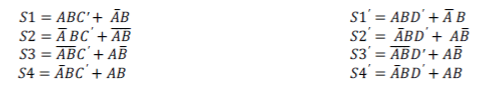
| HMC combines SSP, FPWM, and MSPWM that produces SSHM pulses. A simple combinational sequence in a H bridge is given as, | ||||||||||
 |
||||||||||
| where A is an SSP, B is an FPWM, C’ is an MSPWM for cell-I and D’ is an MSPWM for cell-II. If SSP A = 1, then S1, S2, S1’, and S2’ are operated with MSPWM, while S3, S4, S3’, and S4’ are operated at FPWM. If SSP A = 0, then S1, S2, S1’, and S2’ are operated at FPWM, while S3, S4, S3’, and S4’ are operated with MSPWM. Since A is a sequential signal, the average switching frequency amongst the four switches is equalized. Voltage stress and current stress of power switches in each cell is inherently equalized with this modulation. | ||||||||||
FOURIER ANALYSIS |
||||||||||
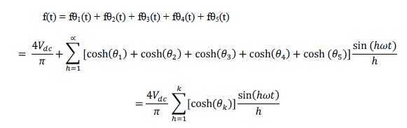
| The Fourier analysis of a multilevel waveform allows the analysis of unwanted harmonics present in the system. The fundamental equations of the Fourier analysis that describe the multilevel waveform is presented . The Fourier series of a cascaded multilevel waveform with separate equal dc sources may be expressed as | ||||||||||
 |
||||||||||
| Where | ||||||||||
| h=odd harmonics(1,3,5,7,…….) | ||||||||||
| s=no of sources | ||||||||||
| θK=firingangle | ||||||||||
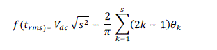
| The total rms value for the multi level waveform with n steps was found by integrating the multilevel waveform over one cycle.The root-mean-square of the cascaded multilevel waveform with n step is | ||||||||||
 |
||||||||||
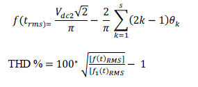
| Fundamental value of rms is given as | ||||||||||
 |
||||||||||
| The quality of a multilevel waveform depends on the choice of switching angles ,varying the switching angles to control the magnitude of the rms waveform also affects the THDv. Ideally, one desires only the fundamental component of the multilevel waveform, and to eliminate or filter the residual frequencies. | ||||||||||
SIMULATION FOR 13 LEVEL INVERTER WITH HYBRID MODULATION TECHNIQUE |
||||||||||
| The simulation diagram of the cascaded H-bridge inverter of 13 level with reduced number of switches .The hybrid modulation scheme consist of the two pair of switches of a single H-bridge, the first pair of switches say s1 and s3 will get commutated by the fundamental pulse width modulation and next two pair of switch say s2 and s4 are being modulated, therefore the resultant switching patterns are the same as those obtained with PSPWM. | ||||||||||
OUTPUT VOLTAGE WAVEFORM |
||||||||||
| The output voltage waveform for the 13 level inverter with hybrid modulation technique is shown in figure6 . | ||||||||||
OUTPUT WAVEFORM FOR HARMONICS |
||||||||||
| The harmonic waveform for thirteen level inverter is about 4.44% for resistive load. | ||||||||||
THD SPECTRUM FOR THIRTEEN LEVEL MULTILEVEL INVERTER OUTPUT VOLTAGE |
||||||||||
| The total harmonic distortion obtained for the proposed method is about 4.44% when compared to the conventional method of 7 level multilevel inverter. | ||||||||||
| The comparison table for the conventional and proposed method is given as | ||||||||||
CONCLUSIONS |
||||||||||
| A new method of multilevel inverter with reduced number of switches has been designed that uses hybrid modulation technique which reduces the power loss and conduction loss. As the circuit when designed with reduced number of switches the conduction and switching losses gets decreased, which leads to increase the efficiency of the inverter. The size and power consumption in the driving circuits can also be minimized. This structure minimizes the Total Harmonic Distortion (THD) of the output voltage waveforms to 4.44%. | ||||||||||
Tables at a glance |
||||||||||
|
||||||||||
Figures at a glance |
||||||||||
|
||||||||||
References |
||||||||||
|


