Keywords
|
| LEACH, energy-efficiency, EECHS, wireless sensor networks |
INTRODUCTION
|
Wireless Sensor Network (WSN) is a wireless network that has spatially distributed sensor devices to sense various
environmental conditions and accumulate the sensed data at a central location, such as a Base Station (BS). Since
energy is an important factor in WSN design, a number of routing protocols have been proposed, that aim to achieve
minimum energy consumption and hence, maximize network lifetime,. Generally, data aggregation and hierarchy are
used in WSNs to reduce energy consumption [3]. |
LEACH [2] is a hierarchical based routing protocol for WSNs. One of the drawbacks of LEACH is the random
election of CHs leading to imbalance in the energy level of the sensor nodes [1]. In EECHS [1], the CHs are chosen
considering the factor of residual energy at each node, distance of the node from the BS and the number of consecutive
rounds in which the node has not been a CH. Thus, EECHS algorithm improves the CH selection strategy and
minimizes energy consumption in the network as shown by simulation results. |
IMPORTANCE OF HIERARCHICAL PROTOCOLS IN WSNS
|
Routing protocols for WSNs are classified based on network structure as flat, hierarchical and location-based. In
particular, hierarchical routing is an efficient way of reducing energy consumption by means of data aggregation and
data fusion, which minimizes the number of messages transmitted to the BS. Hierarchical routing is divided into two
levels: One is used to select the CHs and the other one is used for routing in particular. Hence, cluster formations and
special task assignments to CHs can specifically contribute to increasing the scalability, lifetime, and energy efficiency
of the whole network. |
The important advantages of using clustering techniques in WSNs are as follows: (i) Clusters make the WSN more
scalable, i.e., it can localize the route set up within the cluster and thus reduce the size of the routing table stored at the
individual sensor nodes [4]. (ii) Data aggregation/fusion performed by the CH removes redundancy in data
transmission from CH to the BS. (iii) Clustering techniques help to increase network lifetime. The reduced energy
consumption due to clustering techniques causes an increase in the lifetime of the network. Thus, hierarchical protocols
reduce energy consumption and increase network lifetime and scalability. |
LEACH AND IT’S DESCENDANTS
|
Heinzelman [2] introduced a hierarchical clustering algorithm for sensor networks, called Low Energy Adaptive
Clustering Hierarchy (LEACH). LEACH is a protocol based on clusters. It handles the distributed information from the
clusters. LEACH randomly selects a few sensor nodes as cluster heads (CHs) and rotates this role to evenly distribute
the energy consumption among the sensors in the network. |
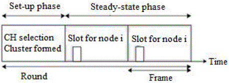
LEACH’s operation is divided into rounds. Each round is divided into two phases: set-up phase and the steady-state
phase. CHs are chosen in the set-up phase and the data are transferred from the nodes to the CH and onto the BS during
steady-state phase. |
In LEACH, cluster-heads are stochastically selected. In order to select cluster-heads each node n determines a
random number between 0 and 1. If the number is less than a threshold T(n), the node becomes a cluster-head for the
current round. |
| The threshold for LEACH is given as [2]: |
 (1) (1) |
with p as the cluster-head probability, r as the number of the current round and G as the set of nodes that have not been
cluster-heads in the last 1/p rounds. This algorithm ensures that every node becomes a cluster-head exactly once within
1/p rounds. |
In LEACH, the cluster head (CH) nodes compress data arriving from nodes that belong to the respective cluster, and
send an aggregated packet to the base station in order to reduce the amount of information that must be transmitted to
the base station. However, data collection is centralized and is performed periodically. Therefore, this protocol is most
appropriate when there is a need for constant monitoring by the sensor network. A user may not need all the data
immediately. Hence, periodic data transmissions are unnecessary which may drain the limited energy of the sensor nodes. After a given interval of time, a randomized rotation of the role of the CH is conducted so that uniform energy
dissipation in the sensor network is obtained. |
LEACH has a few drawbacks. Firstly, the random election of CHs causes an imbalance in the energy consumption
of the sensor network. Secondly, the threshold T(n) is function of only the CH probability, p and the number of the
current round, r. |
To overcome the shortcomings of LEACH mentioned above, improvised versions of LEACH have been proposed
and a few of them are as follows [5-8]: |
• LEACH-C: This protocol uses a centralized clustering algorithm and the same steady-state phase as
LEACH. LEACH-C protocol can produce better performance by dispersing the cluster heads throughout the
network [5]. |
• TL-LEACH: CH collects data from other cluster members as original LEACH [2], but rather then transfer
data to the BS directly; it uses one of the CHs that lies between the CH and the BS as a relay station [6]. |
• Multihop-LEACH: This protocol selects optimal path between the CH and the BS through other CHs and
use these CHs as a relay station to transmit data over through them [7]. |
• VLEACH: In V-LEACH [8], besides having a CH in the cluster, there is a vice-CH that takes the role of
the CH when the CH dies. |
• EECHS-LEACH: In this protocol, [1] it considers residual energy of the nodes, distance between the
nodes and the BS, the number of consecutive rounds in which a node has not been a CH, as parameters in
time of CH selection. |
In EECHS [1], LEACH’s stochastic cluster head selection algorithm is extended by adjusting the threshold T(n)
denoted in equation (1), considering residual energy of the nodes, distance between the nodes and the base station and
the number of consecutive rounds in which a node has not been a cluster head as parameters. Therefore, |
 |
| Here, residual energy factor is |
 (3) (3) |
where Eresidual is the remaining amount of energy and Einitial is the initial energy of node before transmission. Variable i
indicates the serial number of nodes. |
| Here, the distance factor is |
 (4) (4) |
| where diB is the distance from node i to BS as follows: |
 (5) (5) |
| and dFarthest is the distance of the farthest node from the BS. Here (<XBS,YBS>) is the location of the Base Station. |
In third parameter (s div r) of equation (2), s is the number of consecutive rounds in which a node has not been a cluster
head and r is the number of the current round. And p, n and G express the same meaning as in equation (1). |
NETWORK MODEL
|
A few reasonable assumptions of the network model are made based on [1] and they are:
(i)There exists only one base station and it is fixed at a far distance from the sensor nodes. (ii)The sensor nodes are
homogeneous and energy constrained with uniform energy. (iii)Sensor nodes are immobile and all nodes are able to
reach BS. (iv)The RAM size for each node must be sufficient enough to store the distance of the node from BS. |
RADIO ENERGY DISSIPATION MODEL
|
The four main components of a typical sensor node are: a data processing unit, a sensor unit, a radio communication
subsystem that consists of transmitter/ receiver electronics, antenna, and amplifier; and a power supply unit. The energy
dissipation associated with the radio component is mainly considered although energy is dissipated by the first three
components of a sensor node. |
A simple model for the radio hardware energy dissipation is assumed where the transmitter dissipates energy to run
the radio electronics [5]. |
Here, both free space (fs) and multipath (mp) fading channel models have been used, depending on the distance
between the transmitter and receiver, for simulation. If the distance is less than a threshold, the free space (fs) model is
used; otherwise, the multi path (mp) model is used [5].Thus, to transmit a k-bit message over a distance d, the radio
expends: |
 (6) (6) |
 (7) (7) |
| Where the threshold d0 is given as: |
 (8) (8) |
| To receive the message, the radio expends: |
 (9) (9) |
SIMULATION RESULTS
|
The simulation environment is composed of 100 sensor nodes and they are distributed in a region of 100mX100m.
Table 1 lists the simulation parameters. |
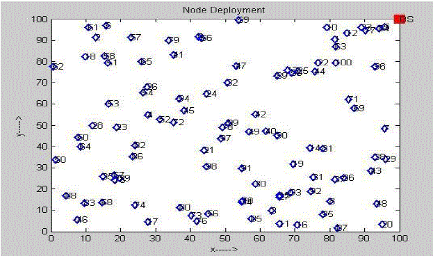
Figure 3 shows the randomly distributed 100 sensor nodes in a 100mX100m area with the Base Station (BS) located
at the coordinates (100,100). |
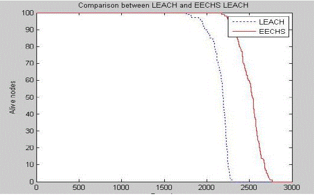
Figure 4 shows the plot of number of alive nodes in the network versus number of rounds, for LEACH and EECHSbased
LEACH protocol. From the plot it is seen that, EECHS shows better performance than LEACH. |
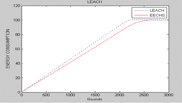
Figure 5 shows the amount of Energy consumption of LEACH and EECHS-based LEACH based on number of
rounds. EECHS shows better performance than LEACH. |
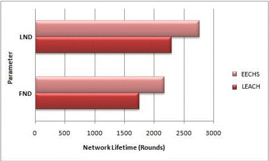
Table 2 shows the comparison of network lifetime with respect to the parameters FND and LND for LEACH and
EECHS-based LEACH. |
Figure 6 shows a bar graph representation of the network lifetime. As indicated in the graph, the network lifetime is
prolonged in EECHS LEACH [1] when compared to LEACH protocol [2]. |
Table 3 shows the comparison of network lifetime with respect to parameters FND and LND, for different amounts
of initial energy of the node. |
CONCLUSION
|
This paper presents a comparison between LEACH and an improved version of LEACH known as EECHS [1]. In
EECHS, selection of the CH differs from that in LEACH in the set-up phase. The steady-state phase in EECHS is same
as in LEACH. The CH selection in EECHS considers residual energy of the node, the distance of the node from the BS
and the number of rounds in which the node has not become CH, which results in the minimization of energy
consumption in the WSN. This is because EECHS improves LEACH protocol by improving the CH selection
algorithm. |
Simulation results show that EECHS exhibits better performance than LEACH with respect to the number of alive
nodes and energy consumption, with number of rounds as the reference. Here, EECHS is 23.96% better than LEACH
with respect to the parameter FND. And, EECHS is 20.55% better than LEACH with respect to the parameter LND. |
ACKNOWLEDGMENT
|
The authors wish to thank Prof. B.V. Nityananda, Head of the Department, Department of E & C, St. Joseph
Engineering College, Mangalore, for his support and valuable inputs. |
| |
Tables at a glance
|
|
|
| |
Figures at a glance
|
 |
 |
 |
| Figure 1 |
Figure 2 |
Figure 3 |
|
| |
 |
 |
 |
| Figure 4 |
Figure 5 |
Figure 6 |
|
| |
References
|
- A.Ray, D.De “Energy Efficient Clustering Hierarchy Protocol for Wireless Sensor Network”, Proc. IEEE International Conference on Communication and Industrial Application (ICCIA) 2011, pp.1-4.
- W. R. Heinzelman, A. Chandrakasan, and H. Balakrishnan, “Energy-efficient communication protocol for wireless microsensor networks,” in Proceedings of the 33rd Annual Hawaii International Conference on System Siences (HICSS ’00), January 2000.
- A. Joshi, Lakshmi P.M., “A Survey of Hierarchical Routing Protocols in Wireless Sensor Network”, MES Journal of Technology and Management
- Xuxun Liu, A Survey on Clustering Routing Protocols in Wireless Sensor Networks, 2012, ISSN 1424-8220
- W. Heinzelman,A. Chandrakasan, and H. Balakrishnan, , “An Application-Specific Protocol Architecture for Wireless Micro sensor network.” IEEE Transactions on Wireless Communications. 2002, vol.1 .no 4, pp 660-670.
- V.Loscri, G.Morabito and S.Marano. “A Two-level Hierarchy for Low-Energy Adaptive Clustering Hierarchy”, Vehicular Technology Conference, 2005.
- Hang Zhou, Zhe Jiang and Mo Xiaoyan, “Study and Design on Cluster Routing Protocols of Wireless Sensor Networks”, Dissertation,2006.
- M.BaniYassein, A.Alzou’bi, Y.Khamayseh, W.Mardini, “Improvement on LEACH protocol of Wireless Sensor Network(VLEACH)”, International Journal of Digital Content Technology and its Applications, Volume 3,Number 2,June 2009,pp.132-136.
- Jamal, N.Al-Karaki and Ahmed E. Kamal, “Routing techniques in Wireless Sensor Networks: A Survey”, Wireless Communications, IEEE, vol. 11, pp. 6-28, Dec. 2004.
- S. Muthukarpagam, V. Niveditta and Nedunchelivan, (2010) “Design issues, Topology issues, Quality of Service Support for Wireless Sensor Networks: Survey and Research Challenges”, IJCA Journal.
- A. Ray, D. De, “P-EECHS: Parametric Energy Efficient Cluster Head Selection protocol for Wireless Sensor Network”, Int. Jr. of Advanced Computer Engineering & Architecture, Volume 2, No. 2 (June-December, 2012)
- A.Ray, D.De “Energy Efficient Cluster Head Selection in Wireless Sensor Network”, 1st International Conference on Recent Advances in Information Technology, RAIT 2012
- Jamal, N.Al-Karaki and Ahmed E. Kamal, “Routing techniques in Wireless Sensor Networks: A Survey”, Wireless Communications, IEEE, vol. 11, pp. 6-28, Dec. 2004.
- Jim Farmer, “Managing Secure Data Delivery: A Data Roundhouse Model”, August. 2001.
- S. Muthukarpagam, V. Niveditta and Nedunchelivan, (2010) “Design issues, Topology issues, Quality of Service Support for Wireless Sensor Networks: Survey and Research Challenges”, IJCA Journal.
- Luis Javier GarcíaVillalba and Ana Lucila Sandoval Orozco, “Routing Protocols in Wireless Sensor Networks”, October 2009.
- Ana-Belen Garcia-Hernando, JFM Ortega, JML Navarro, Luis R Lopez, Problem Solving for Wireless Sensor Networks, Springer International Edition, 2008
|