With the combination of circuit switching & packet switching in computer networks, control signals are separated from the data and transmitted separately in a common control channel. A variable number of data channels are dynamically assigned to each connection through the network. Channels are quickly switched in to accommodate the data flow through a connection and switched out when they are no longer needed. With this approach, a continuous data stream is not altered as it transverses the network and data channels are efficiently utilized even if the data source is bursty. This approach is compatible with legacy networks and can provide a mechanism for convergence of circuit switching and packet switching.
INTRODUCTION |
THE AIM OF COMPUTER NETWORKS |
| A computer network was usually designed to provide a specific communication service. Networks designed
around a specific service include: the telephone networks, which were designed to support voice over circuit switched
connections; the cable television (TV) networks, which were designed to provide broadcast video; and the Internet,
which was designed to support computer communications using packet switching. Subscribers needed to access
multiple networks in order to obtain a full range of communication services. For both clients and servers, access to the
Internet has usually been provided by circuit switched connections through the telephone networks. Typically, a client
is connected to an Internet service provider (ISP) via a dial-up connection, which usually involves a local (non-toll) call
over a relatively short distance. For servers, both dial-up and permanent (leased line) connections to ISPs over
relatively short distances are common. Data is packet switched as it traverses the Internet from the client’s ISP to the
server’s ISP and vice versa. Very long distances can be covered by data flows through the Internet, with most of the
data flowing in the direction from the server to the client, which is usually referred to as the downstream direction. |
| It is desirable to have a common, integrated network that can provide each subscriber with a full range of
communication services over a single broadband access line. The capacity provided to each subscriber should be
sufficient to accommodate full motion video among other high data rate communication functions. High speed network
access can be provided over twisted pair telephone lines using digital subscriber line (DSL) techniques or over TV
cable using hybrid fiber-coax techniques. The current DSL and HFC(cable modem) implementations provide high
speed access to Internet servers, which can supply audio and video streams in addition to supporting traditional
computer data communications, i.e., file transfers. With these approaches, integrated services can be supported,
however, the supporting networks are not fully integrated. The various networks, including the DSL and HFC access
networks, the circuit-switching voice networks, the broadcast video networks, and the packet-switching Internet,
interface with each other. However, these networks maintain distinct identities. |
LITERATURE SURVEY |
| The integration of network services is hampered by the fact that some services, such as voice, are currently
based on circuit switching, while other services, such as file transfers, are currently based on packet switching. With
integrated services digital networks (ISDN), an attempt was made to establish integrated networks that could support
both voice and data communication services. Narrowband ISDN [1] is primarily based on circuit switching with 64 Kb/s channels assigned to particular connections. The subscriber data rates that can be supported by narrowband ISDN
interfaces are relatively low, and consequently, the video capabilities of ISDN are very limited. Broadband ISDN (BISDN)
[2] was designed to provide data rates that could easily support the full range of services, including full motion
video. B-ISDN is based on a form of packet switching called Asynchronous Transfer Mode (ATM). ATM was
designed to transport all types of data (e.g., voice, video, or computer files) using small, fixed size cells. |
| B-ISDN with ATM has not lived up to its promise and has not been generally accepted as solution to the
integrated services problem. Instead, another approach, which leverages the success of the Internet, is based on packet
switching and the Internet Protocol (IP). This IP-centric approach has gained widespread acceptance. However, in order
to achieve the network performance needed for integrated services, additional protocols beyond IP are required. The
leading approach for providing the required performance is based on multi-protocol label switching (MPLS)[3]. MLSP
moves the integrated network away from the connectionless paradigm of IP and make the integrated services network
not quite IP-centric. |
| Circuit switching networks, such as the telephone networks, establish end-to-end physical layer connections
through the network. Transmission resources, i.e., channels, are dedicated to a particular connection for the duration of
a call. With circuit switching, delays are minimized and fixed. A stream of data can be transported through a circuit
switching network without suffering any distortion. Also, the processing performed by a circuit switching network is
relatively simple and straightforward. On the other hand, the utilization of dedicated channels can be low if there is a
significant variation in the data rate. Consequently, circuit switching networks are inefficient for transporting bursty
data, such as the data flows associated with file transfers. However, packet switching introduces randomly varying
delays into the data stream, which can be problematic for the transmission of continuous data, such as voice and video
data streams. Also with packet switching, decisions with respect to switching (or forwarding) of packets must be made
on the fly based on information contained in the packet header. This complicates data processing in the network. |
| The Internet Engineering Task Force (IETF) is developing network control and signaling standards based on
MPLS that apply to both circuit switching and packet switching. This set of standards, which fall under the collective
heading of generalized MPLS (GMPLS)[4], move networks away from connectionless packet switching to a more
connection-oriented operation and foreshadow the convergence of circuit switching and packet switching. |
COMBINATION OF PACKET SWITCHING & CIRCUIT SWITCHING |
| An integrated services network can be based on circuit switching, as used in narrowband ISDN, or on packet
switching, as used in B-ISDN or IP-centric networks. Another alternative approach, which is the approach followed
here, would involve the convergence of circuit switching and packet switching techniques. |
| This paper proposes a network architecture based for an integrated services network that is based on dynamic
switching of the channels assigned to connections through the network. This network combines the advantages of
circuit switching and packet switching. Channels are quickly assigned to a connection to support a particular data flow
and quickly released when they are no longer needed. Network control and signaling are based on a logical extension of
the GMPLS concept. With the proposed approach, bursty data can be efficiently supported while continuous data
streams are transported through the network without distortion. |
| The proposed network is compatible with legacy telephone networks and with the Internet. To take full
advantage of this network’s capabilities, client and server equipment must be upgraded to incorporate a with packet
switching, transmission resources are dynamically shared based on demand. This makes packet switching efficient for
transporting dynamic channel switching network interface. However, most of the benefit of dynamic channel switching
can be realized if only Internet servers are upgraded and clients continue to operate as they currently do. Consequently,
the proposed approach provides a mechanism for facilitating the convergence of circuit switching and packet switching. |
WORKING OF CIRCUIT SWITCHING NETWORKS |
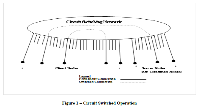
| Circuit switching techniques have been employed by telephone networks for over 100 years.[5] Figure 1
illustrates the operation of a circuit switching network. End-to-end physical layer connections are established between subscriber nodes, which include client nodes, server nodes, and nodes that combine both client and server functions.
For voice operation, a connection is established between peer nodes when one subscriber “calls” another. Data transfers
usually involve a connection between a client and a server, with most of the data flowing downstream from the server
to the client. |
| Each subscriber node has a permanent, dedicated connection to the network, which usually consists of a pair
of copper wires that are twisted together. In the old days a connection was established between subscriber lines by
physically linking wires together through a series of patch panels or electro-mechanical switches so that a closed circuit
was formed with electric current flowing from a subscriber on one end through the network to a subscriber on the other
end, and back again. In today’s networks, the subscriber line on each end is connected to a network channel and
channels are linked together through the network to form a continuous end-to-end channel, or connection. Although the
process of establishing this end-to-end connection is still called “circuit switching”, “channel switching” would be a
more accurate description of what actually takes place within the network. Channels forming the end-to-end connection
are dedicated for the duration of the call. |
| To cause a connection to be set up or released, a subscriber must signal the network.[6] Similarly, control
signals must be transmitted within the network to cause channels to be assigned to a particular connection. Control
signals can be associated with a particular data channel and transmitted in the channel along with the data. Alternately,
a common signaling channel can be used to control multiple data channels. Channel-associated signaling is employed
when a subscriber dials the telephone to provide the network with the information (the telephone number) it needs to
establish a connection. In this case, signaling information is sent from the subscriber to the network in the same band
(or channel) used for voice transmission. Within telephone networks, control information is usually transferred between
nodes over a common signaling channel using the Signaling System Number 7 (SS7) set of protocols.[7] Network
control signals may follow different paths than the data they are controlling. |
 |
| With the advent of ISDN, common channel signaling was extended to the user-to-network interface (UNI).[8]
ISDN provides the user with a separate signaling channel, the D channel, which is used to control the assignment of
data transfer channels (B channels) to a particular connection. Using the D channel signaling, the subscriber can request
that the network allocate additional B channels to an active connection. Unfortunately, most narrowband ISDN
interfaces provide only two B channels to a subscriber, which greatly limits the utility of narrowband ISDN. With BISDN,
data rates and the number of equivalent data channels are greatly increased. However, B-ISDN inexplicably
rejected common channel signaling in favor of ATM.[9] Data is usually transferred digitally through circuit switching networks. With the telephone networks, analog data is usually converted to digital form at the local central office (CO).
In the case of ISDN, and other digital lines, data is already in digital form at the subscriber interface. |
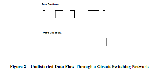
| Delays through circuit switching networks are minimal and fixed. There may be some small buffering delays,
but except for local traffic, these are usually small compared to unavoidable propagation delays. If the bit error rate is
low, which is normally the case, then data will be transported through a circuit switching network without distortion.
This situation is illustrated by Figure 2, where the data stream exiting the network is identical to the data stream
entering the network except for a small fixed delay. This property of the network is important for continuous data
streams, such as those produced by voice and video sources, which can be adversely affected by variable delays. |
 |
| Quality of service (QOS) measures include data rates, delays, delay variations, and error rates. A circuit
switching networks can provide a guaranteed QOS with a fixed data rate, a low fixed delay, and without errors due to
lost or out of order data. These characteristics make circuit switching operation compatible with legacy networks and
most data sources. |
| Compared to packet switching, circuit switching is relatively simple and straightforward to implement. Circuit
switched channels, such as Synchronous Optical Network (SONET) or Synchronous Digital Hierarchy (SDH)
channels, can be readily aggregated, which makes circuit switching networks scalable. If the data rates are high enough,
it would be practical to implement circuit switching with optical components, which is currently not an option for
packet switching. |
| The primary disadvantage of circuit switching is that it is inefficient for transporting bursty data. Channels
with sufficient capacity to handle the required peak data rate for a particular connection must be dedicated to that
connection. If the data rate is bursty, i.e., the peak data rate is much greater than the average data rate, then the channels
assigned to a connection will be underutilized most of the time. This is particularly true for human initiated file
transfers, which tend to be very intermittent and where the utilization may be a few percent or less. For applications
involving continuous data flows, such as voice or streaming audio/video, the percentage variation in the data rate is
much less than the percentage variation for file transfers. Consequently, circuit switching is much more efficient for
continuous data sources than it is for intermittent sources. |
WORKING OF PACKET SWITCHING NETWORKS |
| Packet switching operation involves breaking up data blocks into smaller blocks, or packets, which contain
header and trailers in addition to the data. Packets are switched through the network based on information provided in
the packet headers. With packet switching, transmission resources (channels) are dynamically shared by multiple data
sources rather than being dedicated to a single source. This makes packet switching more efficient than circuit
switching for transporting bursty data. A broad definition of packet switching would include networks based on the
Transmission Control Protocol (TCP)/Internet Protocol (IP), X.25, Frame Relay, Ethernet, and ATM. The Internet can be viewed as a large number of packet switching networks interconnected by routers.[10] These routers use IP as a
common protocol for transferring packets through the Internet. Within the subnets that constitute the Internet, a diverse
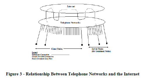
set of protocols, including X.25, Frame Relay, or ATM, are used for transferring packets. Figure 3 illustrates how
clients and servers are connected to the Internet through the telephone networks. Clients typically establish dial-up
circuit switched connections with Internet service providers (ISPs). Servers may be connected to the Internet by dialup
lines (as shown in Figure 3) or by leased lines, or in some cases, servers may be co-located with ISPs. The IP router
at an ISP’s point of presence (POP) can be considered to be the point of entry to the Internet. Within the Internet,
routers are usually connected to each other by leased lines contained within trunks. If these leased lines are viewed as
part of the telephone networks , then data flowing through the Internet would flow into and out of the telephone
networks as illustrated by Figure 3. Even within the individual packet switching networks of the Internet, resources
leased from the telephone networks are often used to establish physical connections. To simplify the figure, these
connections are shown as remaining within the Internet. From the perspective of Figure 3, the Internet is viewed as
being implemented on top of the telephone networks with the Internet being highly dependent on the telephone
networks. The primary rationale for packet switching networks, in general, and the Internet, in particular, is that they do
not require dedicated end-to-end connections between clients and servers. For the most part, physical connections
would be shared rather than dedicated. In Figure 3, the physical connection from the client to the Internet (ISP POP),
which typically would cover a distance of several miles, would usually be dedicated to the flow of data between a
single client and a single server. Physical connections through the Internet, which could cover a distance of thousands
of miles, would be shared by many client/server data flows. For most servers, the physical connection between the
server and the Internet would be shared could be shared by multiple data flows. Thus, packet switching provides a
mean for efficiently utilizing the existing telephone infrastructure without changing it. |
| The TCP/IP approach to packet switching, upon which the Internet is based, offers some particular advantages
compared to alternative packet switching approaches. IP is a connectionless protocol with globally significant addresses
contained in the header of IP packets. This means that IP packets can be treated independently of each other. Much of
the TCP/IP functionality , such as packet sequencing, flow control, and error control, has been assigned to TCP. With
TCP, end-to-end virtual connections, which set parameters for transferring data without assigning physical network
channels, are established between subscribers. With this type of operation, TCP is implemented in the end stations, but
not seen by the network itself. This allocation of functions simplifies processing within the network and facilitates
interfacing between heterogeneous networks. The widespread acceptance of TCP/IP, compared to other packet
switching protocols such as X.25, and the success of the Internet can attributed in part to these advantages. |
 |
| The global addresses in the IP header provide the information required to route packets through the Internet.
The term “routing” usually refers to determining the route that a packet should follow in traversing the network. The
term “forwarding” refers to moving a packet from a particular input port of the router (or more generally, the packet
switch) to a particular output port. Routing requires the exchange of information among Internet routers using protocols
such as the Border Gateway Protocol (BPG) and the Open Shortest Path First (OSPF) protocol.[11] This exchange,
which takes place in the control plane as opposed to the data plane, is analogous to common channel signaling in circuit
switching networks. Forwarding requires processing of information in the packet header, which is linked to data in the packet payload. This linking is analogous to channel-associated signaling in circuit switching networks. Problems
associated with packet switching networks stem largely from the fact that packet switching causes an inevitable
distortion of the stream of data flowing from a data source. With packet switching, data from a source is broken up into
packets and headers and trailers are attached to these packets. Of course, the data can be reassembled to its original
form at the receiving end if uncorrectable errors are not introduced in the transmission process. Consequently, for data
transfers that are not time sensitive, such as most file transfers, en route distortions associated with packet switching are
not usually a problem. However, for continuous data sources, such as voice or streaming audio/video sources,
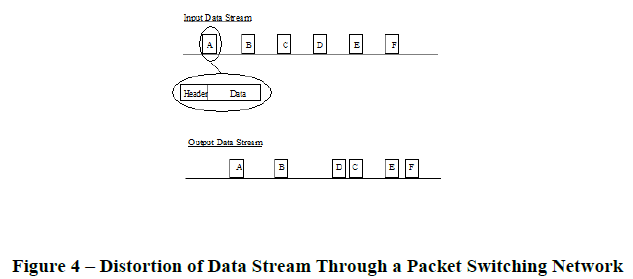
distortions introduced by packet switching can be problematic. For example, consider the data stream shown in Figure
4. In this case, the data stream entering the packet switching network has a uniform spacing between data blocks. A
packet switching network can introduce randomly varying delays, which would cause the data blocks to arrive at the
receiver with a variable spacing and possibly out of order. If the random delay variations are too large, then the data
may arrive too late to be used by a time sensitive application or too much data may arrive too early to be
accommodated by a finite buffer. |
 |
| Even if the bit error rate is close to zero, the distortions of the data stream described above can produce errors
in the received data. Specifically, these errors are the result of lost or out of order packets, discarded late packets, and
buffer overflows. For time insensitive applications, these errors can be corrected by the error control features of higher
layer protocols, such as TCP. However, these errors can adversely affect time sensitive applications, particularly those
applications associated with continuous data sources. In addition to problems associated with errors, packet switching
introduces incompatibilities with existing networks, particularly legacy telephone networks. Generally, telephone
networks receive and deliver data at fixed rates, while packet switching networks generally receive and deliver data at
varying rates. These incompatibilities can be alleviated by buffering the data flow between networks, which introduces
delays. In packet switching networks forwarding decisions must be made on- the-fly. This makes the processing
required for packet switching more complex and demanding than the corresponding processing for circuit switching. In
addition to the generic packet switching problems described above, there are problems specifically related to the
TCP/IP approach. TCP is implemented in the end stations and is not seen by the network. This means that functions
that strongly impact network performance, such as virtual connection establishment (and release) and flow control, are
outside the control of the network. IP, which is a connectionless protocol and has very limited functionality, is the
operative protocol for network elements, specifically network routers. Because of the limitations of IP, it is difficult for
a network relying solely on IP to control congestion and to provide a guaranteed quality of service. Various means
have been suggested for dealing with the packet switching problems described above, particularly the problems
associated with TCP/IP. One approach is to provide a connection oriented capability through the control plan using
Multiprotocol Label Switching (MPLS).[3] MPLS provides a means for establishing virtual connections, which are
called label switched paths (LSPs), through the exchange of control messages among network routers. MPLS uses a
label distribution protocol (LDP), which is a set of procedures by which network elements inform each other of the
meaning of labels used to forward traffic. Transmission resources can be assigned to particular LSPs by exchanging
reservation messages among the routers using the Resource Reservation Protocol (RSVP) .[12] MPLS also defines
generalized labels to be attached to IP packets (and other types of packets). These labels identify that a packet belongs
to a particular LSP requiring a certain category of service and can be used by routers to forward packets without
relying on the full IP addresses. With MPLS and supporting protocols, it becomes more practical to provide a certain
quality of service compared to what can be achieved using IP alone. |
| The IETF is in the process of extending MPLS so that it can be used in a manner similar to circuit switching,
and in particular, the switching of optical channels. Generalized MPLS (GMPLS) provides for implicit labels, which
can be used to associate a data flow with a particular channel. With GMPLS, the control plane is separate from the data
plane so that control signals and data are in different channels and can be processed separately. This type of operation is
similar to common channel signaling approach used in conjunction with narrowband ISDN. One option for GMPLS is
to use RSVP with traffic engineering extensions (RSVP-TE) as the label distribution protocol.[13] |
PRINCIPLES INVOLVED IN DYNAMIC CHANNEL SWITCHING |
| If there were no legacy networks and if a communications network were to be built from scratch, then it would
not make sense to design separate networks, with different protocols, for voice, video, and data communications.
Instead, it would make sense to design an integrated network that would provide a full range of communication services
using common protocols and similar modes of operation. The previous two sections emphasized the significant
differences between circuit switching and packet switching. However, circuit switching and packet switching also have
certain things in common. This section emphasizes this commonality and describes how an ideal network would
combine the features of both circuit switching and packet switching. |
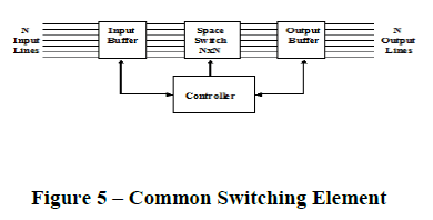
| With both circuit switching and packet switching, signals are switched in both space and time. Figure 5 shows
a common switching element that can be used for circuit switching and/or packet switching. Each of the input lines (or
space channels) is broken up into time intervals (or time channels). If an input signal contains multiple carrier
frequencies or wavelengths, the signal would be converted to signals on multiple lines prior to switching. Thus, a single
fiber containing multiple channels would be equivalent to multiple fibers each containing a single wavelength channel.
The switching element of Figure 5 maps space-time channels at its input onto space time channels at its output. Data on
each of the N input lines would be stored for a short time interval in the input buffer. Data can be read out of the input
buffer in an order different from the order in which it was read in, which would allow time slots to be interchanged.
Data is switched from the input lines to the output lines of the N by N space switch, with the space switching pattern
possibly changing from time slot to time slot. Data exiting the space switch is stored in the output buffer while it is
waiting to be placed on an output line. In reading out the data, the output buffer can perform a second interchange of
time slots. Thus the switch employs three stages of switching, time switching, space switching and time switching
again. With this arrangement of switching elements, blocking within the switch can be eliminated.[14] Thus, data in
any time slot on any input line can be placed in any time slot on any output line. Of course, there would be a conflict if
the switch attempted to map data from two or more inputs onto the same space-time channel at the output. |
| With circuit switching operation, the time slot interchange and space switching functions within the switch of
Figure 5 would be controlled based on information provided in the signaling channels. The controller would monitor
the signaling channels and would determine the switching pattern for mapping input space-time channels onto output
space-time channels. This pattern would include time slot interchange parameters for all input and output lines and
space switching parameters for all time slots. With circuit switching, the switching pattern is predetermined for each
connection through the switch. The switching pattern is modified whenever a connection is established or released or
when the number of channels assigned to a connection is varied. The controller would send updated interchange and
switching parameters to the buffers and the space switch, respectively, whenever the switching pattern is modified. |
| Packet switching operation of the switch of Figure 5 would be similar, but more complex. As with circuit
switching operation, time slot interchange and space switching patterns are determined by the controller. Unlike the
circuit switching case, the switching pattern is not predetermined for packet switching operation. Instead the switching
pattern must be determined on-the-fly based on information contained in the packet headers. The controller must read
the header of each packet entering the switch. If the header indicates that the packet is part of an existing data flow, the
routing through the network should already have been determined and the output line should be available in an existing
table. Otherwise the routing of the packet will have to be determined by the routing algorithm, which may involve the
exchange of control messages with other switches. Once the output line for the packet is determined, the controller
must determine when the packet should be read out of the input and output buffers. Also, the packet header may need to
be modified as the packet passes through the switch. The on-the-fly processing described above make the latency and
throughput requirements on the controller considerably more stringent for packet switching compared to the
corresponding requirements for circuit switching. |
| The packet switching operation described in the previous sections and the operation of the common switching
element described above can be improved upon. Normally, the information required to switch or forward a packet is
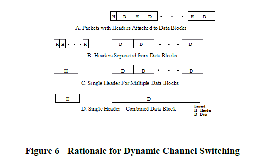
contained in the packet header, which is attached to the data block, as shown in Figure 6A. This means that
switching/forwarding decisions must be made on-the-fly, which imposes strict latency requirements on the switch of
Figure 5. Suppose the headers are sent in advance of the data, as illustrated by Figure 6B. This would allow the switch
to determine the switching pattern in advance of receiving the data, which would allow the latency requirements to be
relaxed. It would also allow the switch to initiate flow control before the actual onset of congestion. |
| Next suppose that instead of sending a separate header for each data block (or packet), multiple headers are
combined into a single header, as illustrated by Figure 6C. This would be particularly advantageous for the case where
multiple successive packets are part of the same data flow and are to be sent to the same destination. Also, combining
of headers would be advantageous for a sequence of packets that are generated at regular intervals. If multiple headers
are combined, the controller could determine the switching patterns for multiple packets at the same time. This would
significantly reduce the computational burden, and the throughput requirement on the controller could be significantly
relaxed. |
| Finally, suppose that multiple data blocks are combined into a single data block, as illustrated by
Figure 6D. At this point, it would no longer be necessary to break source data into packets. Consequently, it would be
possible to directly transmit data as it flowed from the data source. If the bit error rate is low enough and sufficient
network capacity is provided, then the data stream delivered by the network to the receiver would be the same as the
source data stream, except for a small fixed delay. |
RESULTS & DISCUSSION |
| Figure 5 shows a common switching element that can be used for circuit switching and/or packet switching.
Each of the input lines (or space channels) is broken up into time intervals (or time channels). If an input signal
contains multiple carrier frequencies or wavelengths, the signal would be converted to signals on multiple lines prior to
switching. Thus, a single fiber containing multiple channels would be equivalent to multiple fibers each containing a
single wavelength channel. The switching element of Figure 5 maps space-time channels at its input onto space time
channels at its output. Data on each of the N input lines would be stored for a short time interval in the input buffer.
Data can be read out of the input buffer in an order different from the order in which it was read in, which would allow
time slots to be interchanged. Data is switched from the input lines to the output lines of the N by N space switch, with
the space switching pattern possibly changing from time slot to time slot. Data exiting the space switch is stored in the
output buffer while it is waiting to be placed on an output line. In reading out the data, the output buffer can perform a
second interchange of time slots. Thus the switch employs three stages of switching, time switching, space switching
and time switching again. With this arrangement of switching elements, blocking within the switch can be eliminated.
Thus, data in any time slot on any input line can be placed in any time slot on any output line. With circuit switching
operation, the time slot interchange and space switching functions within the switch of Figure 5 would be controlled
based on information provided in the signaling channels. The controller would monitor the signaling channels and
would determine the switching pattern for mapping input space-time channels onto output space-time channels. |
 |
| The packet switching operation described in the previous sections and the operation of the common switching
element described above can be improved upon. Normally, the information required to switch or forward a packet is
contained in the packet header, which is attached to the data block, as shown in Figure 6A. This means that
switching/forwarding decisions must be made on-the-fly, which imposes strict latency requirements on the switch of
Figure 5. Suppose the headers are sent in advance of the data, as illustrated by Figure 6B. This would allow the switch
to determine the switching pattern in advance of receiving the data, which would allow the latency requirements to be
relaxed. It would also allow the switch to initiate flow control before the actual onset of congestion. Next suppose that
instead of sending a separate header for each data block (or packet), multiple headers are combined into a single header,
as illustrated by Figure 6C. This would be particularly advantageous for the case where multiple successive packets are
part of the same data flow and are to be sent to the same destination. Also, combining of headers would be
advantageous for a sequence of packets that are generated at regular intervals. If multiple headers are combined, the
controller could determine the switching patterns for multiple packets at the same time. This would significantly reduce
the computational burden, and the throughput requirement on the controller could be significantly relaxed. Finally,
suppose that multiple data blocks are combined into a single data block, as illustrated by Figure 6D. At this point, it
would no longer be necessary to break source data into packets. Consequently, it would be possible to directly transmit
data as it flowed from the data source. If the bit error rate is low enough and sufficient network capacity is provided,
then the data stream delivered by the network to the receiver would be the same as the source data stream, except for a
small fixed delay |
 |
CONCLUSION |
| This paper presents an approach that combines the advantages of circuit switching and packet switching in an
integrated network. With this approach, control signals are separated from the data and transmitted separately in a
common control channel. Control and signaling operation can be viewed as a logical extension of GMPLS operation. A
variable number of data channels are dynamically assigned to each connection through the network. Channels are
quickly switched in to accommodate the data flow through a connection and switched out when they are no longer
needed. With this dynamic channel switching approach, a continuous data stream is not altered as it transverses the
network and data channels are efficiently utilized even if the data source is bursty. The proposed network is compatible
with legacy networks. To take full advantage of this network’s capabilities, client and server equipment must be
upgraded to support dynamic channel switching. However, most of the benefit of the proposed approach can be
achieved if only server equipment, but not client equipment, is upgraded. In this case, data transport from servers to
clients, which represents the bulk of the data flow, will be enhanced, but client equipment, which represents the bulk of
subscriber equipment, will not be affected. Consequently, the proposed approach provides a mechanism for facilitating
the convergence of circuit switching and packet switching. |
References |
- S. Pandhi, “The Universal Data Connection”, IEEE Spectrum, July 1987.
- Y. Lin, et al, “Fiber-Based Local Access Network Architectures”, IEEE Communications Magazine, Vol. 27, No. 10, October 1989.
- E. Rosen, et al, “Multiprotocol Label Switching Architecture”, IETF Network Working Group, RFC 3031, January 2001.
- A. Banerjee, et al, “Generalized Multiprotocol Label Switching: An Overview of Routing and Management Functions”, IEEE CommunicationsMagazine, Vol. 39, No. 1, January 2001.
- G. Hawley, “Historical Perspectives on the U.S. Telephone Loop”, IEEE Communications Magazine, Vol. 29, No. 3, March 1991.
- J. Martin, Telecommunications and the Computer, Englewood Cliffs, New Jersey: Prentice Hall, 1976, pp. 419-420.
- A. Modarressi and R. Skoug, “Signaling System No. 7: A Tutorial”, IEEE Communications Magazine, Vol. 28, No. 7, July 1990.
- T. Bartee, editor, Digital Communications, Indianapolis, Indiana: Howard W. Sams& Co., 1986, pp. 116-124.
- A. Day, “International Standardization of BISDN”, IEEE LTS – The Magazine of Lightwave Telecommunication Systems, Vol. 2, No.3, August 1991.
- W. Stallings, Data and Computer Communications (sixth edition), Upper Saddle River, New Jersey: Prentice Hall, 2000, pp. 536-537.
|