International Journal of Advanced Research in Electrical, Electronics and Instrumentation Engineering
ISSN ONLINE(2278-8875) PRINT (2320-3765)
ISSN ONLINE(2278-8875) PRINT (2320-3765)
Maria Joseph M1, Siby C Arjun2
|
| Related article at Pubmed, Scholar Google |
Visit for more related articles at International Journal of Advanced Research in Electrical, Electronics and Instrumentation Engineering
For the maximum power savings, inverter fed ac machines are used in industrial applications. The nonlinearities present in inverter cause voltage distortion and unwanted harmonics at the ac machines. In this paper the effect of inverter nonlinearities are studied and different compensation techniques are analysed. Comparative studies of compensation technique were done using MATLAB/Simulink for induction machine as load. Results showing that with compensation technique the voltage distortion and harmonics reduced.
Keywords |
||||||||||||||||||||||
| Inverter nonlinearity, Harmonics, Voltage distortions, Induction machine | ||||||||||||||||||||||
INTRODUCTION |
||||||||||||||||||||||
| Inverter nonlinearities can be considered as the voltage difference between actual value and reference value. Causes for the inverter nonlinearities are dead time, switching delays, voltage drops, and parasitic capacitances. In these dead time is the most important one. Dead time can be defined as the time delay which is given at the inverter switches to avoid shoot through dc link. It causes operation instabilities and torque ripples in ac machines. | ||||||||||||||||||||||
| Basically two types of compensation techniques are available. One is based on average value theory and other is based on pulse correction. In average value theory the lost volt seconds are added vectorially to the voltage reference. In a pulse-based method the compensation is realized for each pulse width modulation (PWM) pulse. Trapezoidal voltage compensation is a method based on average value theory. The lower order harmonics can be controlled by adjusting trapezoid angle. | ||||||||||||||||||||||
| In this paper the effect of dead time in inverter fed induction machine is analysed. And a comparative study of compensation methods has done to find the best method. The compensation strategies are verified by simulations in MATLAB/Simulink. | ||||||||||||||||||||||
ANALYSIS OF DEAD TIME EFFECTS |
||||||||||||||||||||||
| Analysis of the dead-time effects is performed on one phase leg of the three-phase voltage PWM inverter with induction-motor load, where the IGBTs are used as active switching devices. Assume that the phase current is positive when phase current flows from inverter to induction motor as is shown in Fig. 1(b). On the contrary the polarity of the phase current is negative when it flows from induction motor to inverter. When phase current ia is greater than zero, during on-period Ton, upper switch T1 is in on-state and lower switch T4 is in off-state, the current flows to motor through switching device T1. But during dead-time period Td, both switches are in off-state and the phase current can flow through only free-wheeling diodes D4 and the direction of the stator phase current remains unchanged. This phenomenon produces the output voltage error of the inverter. | ||||||||||||||||||||||
| The switching patterns and relationships between ideal and actual output voltages to the positive direction of the phase current ia is shown in Fig. 1(a). The ideal gate signal patterns ‘gate’ and ‘ is shown in Fig. 1(a1), where high level of PWM wave represents turn-on and low level represents turn-off. The real gating signals for the two switches in the presence of a dead-time are shown in Fig. 1(a2). ‘Van’ is the ideal phase output voltage of the inverter. ‘Van1’ is actual output voltage considering the dead time and switching delay as turn-on time ton and turn-off time toff of switches devices. Finally, the difference between ideal and actual inverter output voltages becomes ΔV. It means that there is voltage drop due to the dead time and introduces harmonics at the output of inverters. In case of sensor less inverter fed drives, this distortion usually causes a non optimal motor exploitation at low speed operation. In addition, the motor currents will be distorted, resulting in unnecessary torque ripple. In order to overcome the effect of dead time many approaches have been suggested. | ||||||||||||||||||||||
COMPENSATION TECHNIQUES |
||||||||||||||||||||||
| Inverter nonlinearity compensation techniques are mainly classified as two. Based on average value theory different compensation methods are there for dead time effect [1].-[4] Trapezoidal voltage is one method based on this theory. | ||||||||||||||||||||||
A. Trapezoidal Voltage Compensation |
||||||||||||||||||||||
| Trapezoidal voltage compensation is a method used to compensate for the low-order harmonics from the inverter nonlinearity. In this method, the nonlinearity is regarded as voltage distortions.And the trapezoidal voltage utilized to compensate for the dead time effect. It adapts to varying operating conditions without the aid of any observers & the physical parameters are not necessary [5]. | ||||||||||||||||||||||
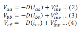
| To analyse the effect of inverter nonlinearity in ac machine induction machine is taken as an example. The inverter nonlinearity is entirely separated as the nonlinear loads d(ias), d(ibs), d(ics) .An averaged model of the inverter was taken and averaged for one sampling period, to consider the temporal distortions. These distortions can also be separated from the inverter and are reflected on the nonlinear loads, D (ias), D (ibs), and D (ics) as shown in Fig. 2.a. Since the inverter nonlinearity is entirely separated as the nonlinear loads, pole voltages can be synthesized equal to their references in the circuit in Fig. 2.b this is summarized in equation (1). | ||||||||||||||||||||||
| The superscript “*” denotes the reference value. The compensation principle is clarified with Fig. 3. | ||||||||||||||||||||||
 |
||||||||||||||||||||||
| Where D (ias), D (ibs) and D (ics) is the distorted voltages. | ||||||||||||||||||||||
1) Distorted Voltage under the Stationary Condition |
||||||||||||||||||||||
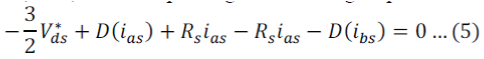
| The back electromotive force (EMF) of an induction machine is zero under the stationary condition. Furthermore, voltage drops on the inductances of the IM can also be ignored in the average sense when the currents are regulated as dc values by a pulse width modulation (PWM) of VSI. Under these conditions, the IM can be modelled as a three-phase resistive load, and the voltage reference would be in phase with the output current. | ||||||||||||||||||||||
| Applying Kirchhoff’s voltage law (KVL) to the loop in Fig. 5, the voltage equation can be derived as | ||||||||||||||||||||||
 |
||||||||||||||||||||||
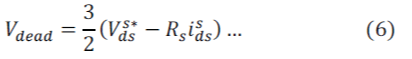
| Where Rs is the equivalent resistance, which includes the resistances of the IM and switch modules. If the distortion from the dead time is only considered, the distorted voltage can be assumed as a constant Vdead. | ||||||||||||||||||||||
 |
||||||||||||||||||||||
| 2) Shape of The Compensation Voltage (CV) | ||||||||||||||||||||||
| The trapezoidal voltage, CV in Fig. 5, was utilized for the compensation .This voltage should be in phase with the output current and trapezoidal angle ÃÂôt can be adjusted for the suitable compensation. The low-order harmonics of the trapezoidal voltage, except for the fundamental, can be modulated by adjusting ÃÂôt. In the conventional methods, ratios of the low-order harmonics to the fundamental can be considered as being fixed once the compensation voltage is determined. This distinction can facilitate the adaptation of the proposed method to varying operating conditions. Namely, the magnitude of the harmonic voltages for the compensation can be appropriately modulated through adjusting ÃÂôt even if magnitude of the harmonic distortions from the inverter nonlinearity is changed due to altered operating conditions. | ||||||||||||||||||||||
4) Modulation of The Compensation Voltage |
||||||||||||||||||||||
| The phase angle of the output current should be identified for to synchronize the trapezoidal voltage with the output current, and to modulate the trapezoidal angle. Trapezoidal angle of the compensator can be adjusted by using a modulator. | ||||||||||||||||||||||
| B. Pulse Based Dead Time Compensation | ||||||||||||||||||||||
| Another method for dead time compensation is based on PWM pulse correction. This technique is developed by analysing the effects of dead time on a pulse by pulse basis and correcting each pulse accordingly. By modifying the switching times to compensate for the dead time effect, the output voltage can be properly controlled in magnitude and phase. The Pulse based dead time compensator updates the turn-on time of the power device at the beginning of a PWM cycle and the turn-off time of the device at the midpoint of the PWM cycle by software correction. Correction is based on the polarity of the currents, independent of operating or carrier frequencies. The method does not need current phase detection, thus eliminating the analog to digital converters and software overhead of other methods. The effects of the dead time on the output voltage can best be examined from one phase of the PWM inverter. | ||||||||||||||||||||||
| Fig. 6(1) show the pulse time correction using the Pulse based dead time compensator for ia> 0. Fig. 6(a) is the ideal pulse time for T1 as T1 transitions from off to on and from on to off. Fig. 6(b) shows the pulse after the dead time counter if allowed to be processed by the PWM waveform generator without correction. Fig. 6(c) shows the error pulse (6(a) - 6 (b)) due to the dead time. To correct the error, the software algorithm adjusts the pulse time width. For ia> 0, time is added to the pulse before the dead time generator creating an unsymmetrical pulse. The increased pulse time (6(d)) is processed through the dead time counter. The actual pulse (6(e)) is identical to the ideal pulse time (6(a)) in width and position [6]. | ||||||||||||||||||||||
| Fig. 6(2) shows the operation of the Pulse based dead time compensator for ia< 0. The correction is similar to ia> 0 in Fig. 6 (1), except time is subtracted from the pulse. Fig. 6(a) is the ideal pulse time. Fig. 6(b) shows the ideal pulse time after the dead time. Fig. 6(c) shows the error pulse (6(a) - 6(b)) due to the dead time. The reduced pulse time (6(d)) is processed through the dead time counter. The actual pulse (6(e)) is identical to the ideal pulse time (6(a)) in width and position. The Pulse Based Method offers the ability to modify the switching dead times to account for dissimilar turnon and turn-off characteristics of the power devices, thus eliminating the need for power device measurements. | ||||||||||||||||||||||
MATLAB ANALYSIS FOR DEAD TIME EFFECTS AND COMPENSATION TECHNIQUES |
||||||||||||||||||||||
A. Analysis of Inverter Fed Induction Machine (IM) With Dead Time |
||||||||||||||||||||||
| A three-phase motor rated 10HP, 460 V; 1500 rpm is fed by a PWM inverter. The PWM inverter is built entirely with standard Simulink blocks. Its output goes through Controlled Voltage Source blocks before being applied to the IM block's stator windings. The load torque applied to the machine's shaft is originally set to its nominal value (4 N.m). The current control loop regulates the motor's stator currents. | ||||||||||||||||||||||
B.Trapezoidal Voltage Compensation |
||||||||||||||||||||||
| To compensate the effect of inverter nonlinearity is trapezoidal voltage compensation which is mentioned in previous chapter was simulated in MATLAB. Fig. 8 shows an IM fed from an inverter. A compensation voltage generated from trapezoidal compensator block is added with the output from controller. Compensation voltage magnitude (Vcom) and angle (ÃÂôt ) generated from trapezoidal compensator block. By using a wave generation program trapezoidal voltage is generated. Switching pulses for the inverter is generated by using PWM block. Reference value for the PWM pulse generation is obtained from current controller output. Hysteresis controller is used for current control. The machine used has same parameter as in the above simulation. | ||||||||||||||||||||||
C.Pulse Based Dead Time Compensation |
||||||||||||||||||||||
| Another way for the inverter nonlinearity compensation pulse based dead time compensator. Pulse correction is done at ‘dead time compensation’ block. | ||||||||||||||||||||||
RESULT ANALYSIS |
||||||||||||||||||||||
| Fig.10 infers that dead time of 5μs introduces waveform distortion as well as harmonics at the output current. The stator current gets distorted and efficiency of the system gets reduced by the addition of dead time in the inverter switches. When analyzing the harmonics, the lower order harmonics are more than higher order harmonics. In that 5th,7th ,11th,13th harmonics are dominant. | ||||||||||||||||||||||
| With compensation technique waveform distortion and harmonic value are reduced (see Fig.11). | ||||||||||||||||||||||
| With pulse base correction waveform distortion is reduced more than trapezoidal method. Stator current output is steadier with pulse base method. The harmonic analysis for both the methods is as follows.5th,7th and 13th order harmonic value are less for pulse based method of correction. But 7th order value is 0.0.1% for pulse base method. And from the total analysis pulse base method is found to be more effective solution for inverter dead time compensation. | ||||||||||||||||||||||
CONCLUSION |
||||||||||||||||||||||
| Inverter nonlinearity introduces waveform distortion and harmonics at the output current of inverter fed induction machines. Analysis of effect of dead time in drives was done with MATLAB/Simulink. The compensation techniques were implemented And results shows that with both the method compensation is good. While comparing both the methods Pulse based method of correction is found to be more effective method for inverter nonlinearity compensation. | ||||||||||||||||||||||
ACKNOWLEDGMENT |
||||||||||||||||||||||
| We thank the Almighty for His enlightening presence and blessings throughout our life and for helping us to complete this paper work successfully. We would like to thank our family and friends for their continuous support and prayers. | ||||||||||||||||||||||
Tables at a glance |
||||||||||||||||||||||
|
||||||||||||||||||||||
Figures at a glance |
||||||||||||||||||||||
|
||||||||||||||||||||||
References |
||||||||||||||||||||||
|


