International Journal of Advanced Research in Electrical, Electronics and Instrumentation Engineering
ISSN ONLINE(2278-8875) PRINT (2320-3765)
ISSN ONLINE(2278-8875) PRINT (2320-3765)
Neha Kaushik1,Dr. M. K. Soni2, Ashish Grover3
|
| Related article at Pubmed, Scholar Google |
Visit for more related articles at International Journal of Advanced Research in Electrical, Electronics and Instrumentation Engineering
Due to limited non-renewable energy sources, today we are focussing towards the advent use of renewable sources like wind, solar, tidal etc. wind is becoming the most promising one. In this paper the variable speed of wind turbine is controlled by interfacing induction generator with power electronics and different control techniques. This helps in reduction of fluctuations in variable speed wind turbine, harmonics and sinusoidal electrical energy to be penetrated in to the load/grid. Through the means of power electronics we can make wind energy a prime renewable energy source world-wide. Thus prelation of wind energy can also become a key to power system operation.[2]
Keywords |
||||||||||||||||||||||
| Wind energy, Induction generator, PWM, SVPWM, inverter, vector control. | ||||||||||||||||||||||
INTRODUCTION |
||||||||||||||||||||||
| In recent years, wind energy has become one of the most important and promising sources of renewable energy, which demands additional transmission capacity and better means of maintaining system reliability. Conservation of nonrenewable resources motivate to explore the new avenues of resources for electricity generation which could be clean, safe and most valuable to serve the society for a long period. The installed capacity increased from a modest base of 41.3 MW in 1992 to reach 17,351MW by December 2012. The evolution of technology related to wind systems industry leaded to the development of a generation of variable speed wind turbines that present many advantages compared to the fixed speed wind turbines. Induction generators cannot generate power on their own without some form of reactive power for excitation which has to be provided through the stator winding. When the induction machine is driven by an external prime mover, the flux in the rotor induces a small voltage in the stator windings. The statorwinding voltage has a leading current if a suitable source of reactive power is connected to the terminal. The source of reactive power could be a synchronous generator, a bank of capacitors, or an inverter. | ||||||||||||||||||||||
RELATED WORK |
||||||||||||||||||||||
| Previously many techniques related to SPWM and SVPWM is described which has solved issues of total harmonic distortion (THD) and also controlled active and reactive power. Most modern turbine inverters are forced commutated PWM inverters to provide a fixed voltage and fixed frequency output with a high power quality.The paper discuss about the various schemes of PWM along with vector control with IGBT inverter which has better computational time and also fixed the magnitude of voltage and current. | ||||||||||||||||||||||
WHY INVERTERS ARE PREFFERED? |
||||||||||||||||||||||
| Today, most turbines operate at variable-speed, and the control system regulates the rotor speed to obtain peak efficiency in fluctuating winds by continuously updating the rotor speed and generator loading to maximize power and reduce drive train transient torque loads. Operating variable speed requires the use of inverters to make the generated power match the grid frequency. The inverter also enables turbines to deliver fault ride through protection, voltage control, and dynamic reactive power support to the grid.[1] | ||||||||||||||||||||||
| The major components of a typical wind energy conversion system include a wind turbine, generator, interconnection apparatus and control systems, as shown in Fig.1. For wind generation ac-dc-ac inverters are combined with various advanced control techniques interfaced with power electronics devices. This progressively helps in variable speed operation. In this way electrical grid frequency and mechanical rotor speed is separated. The accurate controls of voltage and frequency can limit the electrical and mechanical stresses in the power system and delivering good quality energy. Various PWM techniques used to obtain the required voltage in inverter terminals. The variable output voltage of the generator is rectified and inverted using the PWM inverter. The modulation index adjusted such that the voltage at the output has maintained.[3] | ||||||||||||||||||||||
TYPES OF WIND TURBINE |
||||||||||||||||||||||
| Wind turbines are basically classified into two types namely | ||||||||||||||||||||||
| 1. Fixed speed wind turbine | ||||||||||||||||||||||
| 2. Variable speed wind turbine | ||||||||||||||||||||||
I Fixed speed wind turbine(TYPE 1) |
||||||||||||||||||||||
| The fixed-speed wind turbine consists of a rotor and an induction generator directly connected to grid via gear box shown in fig.2.It contributes to system frequency support because each wind turbine generator (WTG) is directly connected to the power grid. The generator slip is varied so speed is not or speed variation is very small (1-2%) so this is called ‘fixed-speed’ wind turbine.[5] | ||||||||||||||||||||||
II Variable speed wind turbine(TYPE 2) |
||||||||||||||||||||||
| Variable speed configurations provide the ability to control the rotor speed. Variable speed operation can only be achieved by decoupling electrical grid frequency and mechanical rotor frequency shown in fig.2. To this end, power electronic converters are used, such as an AC-DC-AC converter combined with advanced control systems. | ||||||||||||||||||||||
| The following advantages of Variable speed wind turbine over Fixed speed wind turbine are as follows: | ||||||||||||||||||||||
| ïÃâ÷ The Annual Energy Production (AEP) increases because the turbine speed can be adjusted as a function of wind speed to maximize output power. Depending on the turbine aerodynamics and wind regime, the turbine will on average collect up to 10% more annual energy. | ||||||||||||||||||||||
| ïÃâ÷ The mechanical stresses are reduced due to the compliance to the power train. The turbulence and wind shear can be absorbed, i.e., the energy is stored in the mechanical inertia of the turbine, creating a compliance that reduces the torque pulsations. | ||||||||||||||||||||||
| ïÃâ÷ The output power variation is somewhat decoupled from the instantaneous condition present in the wind and mechanical systems. When a gust of the wind arrives at the turbine, the electrical system can continue delivering constant power to the network while the inertia of mechanical system absorbs the surplus energy by increasing rotor speed. Comparison shown in fig.3. | ||||||||||||||||||||||
| ïÃâ÷ Power quality can be improved by reduction the power pulsations. This allows increasing the penetration of the wind power in the network.[6] | ||||||||||||||||||||||
METHODOLOGY |
||||||||||||||||||||||
| In this paper the four different PWM control strategies has been discussed. Different inverters are used with induction generator which is used to control the wind turbine. They are as follows | ||||||||||||||||||||||
| ïÃâ÷ SPWM(Sinusoidal Pulse Width Modulation) with universal bridge | ||||||||||||||||||||||
| ïÃâ÷ PWM(Pulse Width Modulation) with IGBT inverter | ||||||||||||||||||||||
| ïÃâ÷ SV PWM(Space Vector Pulse Width Modulation) with MOSFET inverter | ||||||||||||||||||||||
| ïÃâ÷ Vector Control with IGBT inverter | ||||||||||||||||||||||
A. SPWM with universal bridge |
||||||||||||||||||||||
| The system consists of two independent circuits illustrating two three-phase two-level PWM voltage source inverters. Each inverter feeds an AC load (1 kW, 500 var 60Hz @ 208V rms). Three phase universal bridge rectifier is used to convert the variable voltage and variable frequency at the induction generator terminal into rectified dc voltage converters are controlled in open loop with the Discrete PWM Generator. The simulated result shown in Fig.4 shows the input PWM voltage and the simulated output load voltage. The output voltage is in the form of pulses. | ||||||||||||||||||||||
B. PWM with IGBT inverter |
||||||||||||||||||||||
| Fig.5 shows a 60 Hz, induction machine feeds a 50 Hz, 50 kW load through an AC-DC-AC converter. The filtered DC voltage is applied to an IGBT two-level inverter generating 50 Hz. The IGBT inverter uses Pulse Width Modulation (PWM) at a 2 kHz carrier frequency. The load voltage is regulated at 1 pu (380 V rms) by a PI voltage regulator using abc_to_dq and dq_to_abctransformations. The first output of the voltage regulator is a vector containing the three modulating signals used by the PMW Generator to generate the 6 IGBT pulses. The second output returns the modulation index. The Multimeter block is used to observe diode and IGBT currents. In steady state, the mean value of the modulation index is m = 0.80 and the mean value of the DC voltage is 778 V. The fundamental component of 50 Hz voltage buried in the chopped inverter voltage is therefore: Vab = 778 V * 0.612 * 0.80 = 381 V rms | ||||||||||||||||||||||
| The filtered dc voltage is applied to IGBT is shown in fig.6 above than inverter output voltage is shown in pulse form. After that output load voltage is shown and then modulation index is maintained at 1. The output voltage is improved than in the above scheme as it is becoming steady and constant with time. | ||||||||||||||||||||||
| Fig.7 shows the switching time of diode (above) and IGBT (below). The pink pulse shows switching time of diode 1 and IGBT 1 respectively in both the graphs and switching time shown in yellow I of diode 3 and IGBT 3. | ||||||||||||||||||||||
C. SV PWM with MOSFET inverter |
||||||||||||||||||||||
| A 3-phase squirrel-cage induction generator rated 3 HP, 220 V, 60 Hz, 1725 rpm fed a 3-phase MOSFET inverter connected to a DC voltage source of 325 V. The inverter is modelled using the "Universal Bridge" block and the "Asynchronous Machine" block. Its stator leakage inductance Lls is set to twice its actual value to simulate the effect of a smoothing reactor placed between the inverter and the machine. The load torque applied to the machine's shaft is constant and set to its nominal value of 11.9 N.m. The firing pulses to the inverter are generated by the "Space-Vector PWM modulator" block. Speed control of the machine is performed by the "Constant V/Hz" block. The magnitude and frequency of the stator voltages are set based on the speed set point. By varying the stator voltages magnitude in proportion with frequency, the stator flux is kept constant. | ||||||||||||||||||||||
| Fig. 8 shows the stator input voltage which is 320Vrms. The graph below shows the stator input current of induction machine. Results came from the Simulink model whose description is given above. | ||||||||||||||||||||||
| Fig.9 shows the speed of the machine which is 1720rpm. The second graph shows the output voltage which is 220 Vrms. Next graph shows the frequency maintained at 60Hz and last graph shows the variation of electromagnetic torque. Here the maximum effective use of input stator voltage is done which made this scheme best among all above. The THD reduction is maximum in this case. | ||||||||||||||||||||||
D. Vector Control with IGBT inverter |
||||||||||||||||||||||
| The induction machine is fed by a current-controlled PWM inverter. The speed control loop uses a proportionalintegral controller to produce the quadrature-axis current reference iq* which controls the torque. A vector-control approach is used, with a reference frame oriented along the stator (or supply) voltage vector position, enabling independent control of the active and reactive power flowing between the supply and the supply-side converter. The PWM converter is current regulated, with the direct axis current used to regulate the DC-link voltage and the quadrature axis current component used to regulate the reactive power. Fig.10 shows the Simulink model of vector control with IGBT inverter based on above description. | ||||||||||||||||||||||
| Fig.11 shows the output voltage of vector control in the form of pulses. The output current shown is more in the starting and then it decreases to a constant value. The rotor speed of the induction machine is increased and maintained constant at higher value according to which the torque is also maintained constant after some time. As the constant output voltage and current is achieved in this scheme this makes it better than SVPWM also. | ||||||||||||||||||||||
COMPARISION |
||||||||||||||||||||||
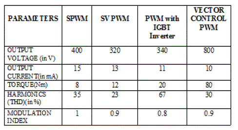
| ïÃâ÷ Modulation Index- The modulation index is almost constant for PWM with IGBT Inverter, higher for SVPWM as compared to SPWM. | ||||||||||||||||||||||
| ïÃâ÷ Computation time- The computation time of vector control takes least time than other scheme. After that SVPWM method takes then PWM scheme and lastly SPWM. | ||||||||||||||||||||||
| ïÃâ÷ Output Voltage - The output voltage is about 15% more in case of SVPWM as compared to SPWM. The output voltage of PWM with IGBT Inverter is less than SVPWM and reaches steady state with time and vector control PWM has highest output voltage. | ||||||||||||||||||||||
| ïÃâ÷ Output current- The output current much less in case of SVPWM then any other method. | ||||||||||||||||||||||
| ïÃâ÷ Torque – torque harmonics produced are much less in case of SVPWM. | ||||||||||||||||||||||
 |
||||||||||||||||||||||
| However despite all the above mentioned advantages that SVPWM enjoys over SPWM, SVPWM algorithm used in three-level inverters is more complex because of large number of inverter switching states. Hence we see that there is a certain trade off that exists while using SVPWM for inverters for Adjustable speed Drive Operations. Due to this we have to choose carefully as to which of the two techniques to use weighing the pros and cons of each method. | ||||||||||||||||||||||
CONCLUSION |
||||||||||||||||||||||
| After study of these kinds of variable speed wind turbines, and how the control techniques actually work on power electronic interface shows really interesting results. All the PWM methods mentioned in this paper are far best for wind turbines to reduce THD and to produce sinusoidal electrical energy. As study reveals Space vector PWM generates less harmonics distortion in current or voltage in comparison with sine PWM but the computation time of vector control is comparatively less. The speed is also become constant after a raise. Space vector provides more efficient use of supply voltage in comparison with Sine PWM [3]. As torque is concerned vector control has maximum. So vector control method can be used over SVPWM and SPWM. | ||||||||||||||||||||||
Figures at a glance |
||||||||||||||||||||||
|
||||||||||||||||||||||
References |
||||||||||||||||||||||
|


