ISSN ONLINE(2278-8875) PRINT (2320-3765)
ISSN ONLINE(2278-8875) PRINT (2320-3765)
P.Ramana1, B.Santhosh Kumar2, Dr.K.Alice Mary3, Dr.M.Surya Kalavathi4
|
| Related article at Pubmed, Scholar Google |
Visit for more related articles at International Journal of Advanced Research in Electrical, Electronics and Instrumentation Engineering
Permanent Magnet Synchronous Motor (PMSM) drives have been increasingly applied in a variety of industrial applications which require fast dynamic response and accurate control over wide speed ranges. However, there still exist challenges to design position-sensor less vector control of PMSM operating in a wide speed range, which covers both constant-torque and constant-power region. Field oriented control (FOC) of permanent magnet synchronous motor (PMSM) is one of the widely used methods for the speed control of the motor. The feasibility and effectiveness of various pulse width modulation techniques implemented for PMSM are addressed in this paper and verified by computer simulation. The whole drive system is simulated in MATLAB/SIMULINK based on the mathematical model of the system devices including PMSM and inverter. The aim of the drive system is to have speed control over wide speed range. Simulation results show that the speed controller has a good dynamic response.
Keywords |
||||||||||||||||||||||||||||||||||||||
| Permanent Magnet Synchronous Motor, Field Oriented Control, Sine Pulse-width Modulation, Space Vector Pulse-width Modulation, Third harmonic injected Pulse-width Modulation | ||||||||||||||||||||||||||||||||||||||
INTRODUCTION |
||||||||||||||||||||||||||||||||||||||
| Permanent magnet synchronous motor drives (PMSM) offers many advantages over the induction motor, such as overall efficiency, effective use of reluctance torque, smaller losses and compact motor size. In recent years many studies have been developed to find out different solutions for the PMSM drive control having the features of quick and precise torque response, and the field oriented control has been recognized as viable and robust solution to achieve these requirements.[2] | ||||||||||||||||||||||||||||||||||||||
| The practical application of the system, using direct torque control, is handicapped by the difficulty of starting under full load due to the unknown initial rotor position. A lot of efforts have been made to detect the initial rotor position. Among them, the most versatile method is to make use of the structural and magnetic saturation saliencies which exist in the PMSM. The structural saliency could be employed to acquire the position of the rotor axis, while the saturation saliency, which is generated by the rotor permanent magnets, can be used to detect the magnetic polarity[1]. The main objective of the vector control is achieved by using a d-q rotating reference frame synchronously with the rotor flux space vector. In ideally, field-oriented control, the rotor flux linkage axis is forced to align with the d-axes. In fieldoriented control, the torque equation becomes analogous to the DC machine [3]. The inverter plays an important role to provide better sinusoidal voltage or current, speed control of machines becomes finer. It is possible only if inverter gets better gate pulses.[4] | ||||||||||||||||||||||||||||||||||||||
| This paper presents a nonlinear model of PMSM, which incorporates both the structural and saturation saliencies to enable the numerical simulation of new rotor position detection. In this model, the self and mutual differential inductances of the phase windings are expressed as functions of the rotor position and stator current. Based on the model, the field oriented control (FOC) scheme is simulated within the MATLAB/ SIMULINK environment. | ||||||||||||||||||||||||||||||||||||||
MATHEMATICAL MODELLING OF PMSM |
||||||||||||||||||||||||||||||||||||||
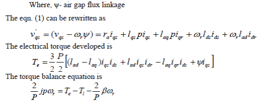
| The voltage equations for the permanent magnet motor in rotor reference frame are | ||||||||||||||||||||||||||||||||||||||
 |
||||||||||||||||||||||||||||||||||||||
 |
||||||||||||||||||||||||||||||||||||||
| Where all voltages (v) and currents (i) refer to the rotor reference frame. The subscripts qs, ds, qr and dr correspond to q and d axis quantities for the stator(s) and rotor(r) in all combinations, ra denotes the armature resistance, lqs denotes quadrature axis inductance, lds denotes direct axis inductance etc. and Te is the developed torque. The rotor speed is given by ωr and the load torque by Tl. J is moment of inertia, P is the number of poles and β is the co-efficient of viscous friction. The derivative operator is represented by the symbol p. | ||||||||||||||||||||||||||||||||||||||
| Representing the voltage eqns. (1)-(5) into a state space representation as given below: | ||||||||||||||||||||||||||||||||||||||
 |
||||||||||||||||||||||||||||||||||||||
FIELD ORIENTED CONTROL (FOC) OF PMSM |
||||||||||||||||||||||||||||||||||||||
| Field Oriented Control demonstrates that an induction motor or synchronous motor could be controlled like a separately excited dc motor by the orientation of the stator magneto motive forces.or current vector in relation to the rotor flux to achieve a desired objective. It usually refers to controllers which maintain a 900 electrical angle between rotor and stator field components. In DC motors, the flux and torque producing currents are orthogonal and can be controlled independently. The magneto motive forces, developed by these currents are also held orthogonal. The torque developed is given by the equation | ||||||||||||||||||||||||||||||||||||||
| Hence the flux is only dependent on the field winding current. If the flux is held constant, then the torque can be controlled by the armature current. For this reason DC machines are said to have decoupled or have independent control of torque and flux. In AC machines, the stator and rotor fields are not orthogonal to each other. The only current that can be controlled is the stator current. Field Oriented Control is the technique used to achieve the decoupled control of torque and flux by transforming the stator current quantities (phase currents) from stationary reference frame to torque and flux producing currents components in rotating reference frame. | ||||||||||||||||||||||||||||||||||||||
Advantages of FOC: |
||||||||||||||||||||||||||||||||||||||
| ïÃâ÷ Transformation of a complex and coupled AC model into a simple linear system | ||||||||||||||||||||||||||||||||||||||
| ïÃâ÷ Independent control of torque and flux, similar to a DC motor | ||||||||||||||||||||||||||||||||||||||
| ïÃâ÷ Fast dynamic response and good transient and steady state performance | ||||||||||||||||||||||||||||||||||||||
| ïÃâ÷ High torque and low current at start up | ||||||||||||||||||||||||||||||||||||||
| ïÃâ÷ High Efficiency | ||||||||||||||||||||||||||||||||||||||
| ïÃâ÷ Wide speed range through field weakening | ||||||||||||||||||||||||||||||||||||||
PULSE WIDTH MODULATION |
||||||||||||||||||||||||||||||||||||||
A. Principle of Pulse Width Modulation (PWM) |
||||||||||||||||||||||||||||||||||||||
| Fig.1 shows circuit model of a single-phase inverter with a centre-taped grounded DC bus, and Fig.2 illustrates principle of pulse width modulation. | ||||||||||||||||||||||||||||||||||||||
| As depicted in Fig. 2, the inverter output voltage is determined in the following | ||||||||||||||||||||||||||||||||||||||
| Also, the inverter output voltage has the following features: | ||||||||||||||||||||||||||||||||||||||
| ïÃâ÷ PWM frequency is the same as the frequency of Vtri | ||||||||||||||||||||||||||||||||||||||
| ïÃâ÷ Amplitude is controlled by the peak value of Vcontrol | ||||||||||||||||||||||||||||||||||||||
| ïÃâ÷ Fundamental frequency is controlled by the frequency of Vcontrol | ||||||||||||||||||||||||||||||||||||||
B. Principle of Sinusoidal PWM |
||||||||||||||||||||||||||||||||||||||
| `Fig. 3 shows circuit model of three-phase PWM inverter and Fig. 4 shows waveforms of carrier wave signal (Vtri) and control signal (Vcontrol), inverter output line to neutral voltages are VA0, VB0, VC0, inverter output line to line voltages are VAB, VBC, VCA respectively. | ||||||||||||||||||||||||||||||||||||||
| `As described in Fig.4, the frequency of Vtri and Vcontrol is | ||||||||||||||||||||||||||||||||||||||
| ïÃâ÷ Frequency of Vtri = fs | ||||||||||||||||||||||||||||||||||||||
| ïÃâ÷ Frequency of Vcontrol = f1 | ||||||||||||||||||||||||||||||||||||||
| Where, fs = PWM frequency and f1 = Fundamental frequency The inverter output voltages are determined as follows: | ||||||||||||||||||||||||||||||||||||||
 |
||||||||||||||||||||||||||||||||||||||
C Principle of Space Vector PWM |
||||||||||||||||||||||||||||||||||||||
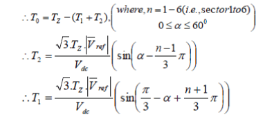
| The circuit model of a typical three-phase voltage source PWM inverter is shown in Fig. 5. S1 to S6 are the six power switches that shape the output, which are controlled by the switching variables a, a′, b, b′ and c, c′. When an upper transistor is switched on, i.e., when a, b or c is 1, the corresponding lower transistor is switched off, i.e., the corresponding a′, b′ or c′ is 0. Therefore, the on and off states of the upper transistors S1, S3 and S5 can be used to determine the output voltage. | ||||||||||||||||||||||||||||||||||||||
| The relationship between the switching variable vector [a, b, c] T and the line-to-line voltage vector [Vab Vbc Vca]T is given as follows | ||||||||||||||||||||||||||||||||||||||
 |
||||||||||||||||||||||||||||||||||||||
| Also, the relationship between the switching variable vector [a, b, c] T and the phase voltage vector [Va Vb Vc] T can be expressed below. | ||||||||||||||||||||||||||||||||||||||
 |
||||||||||||||||||||||||||||||||||||||
| As illustrated in the Fig 6, there are eight possible combinations of on and off patterns for the three upper power switches. The on and off states of the lower power devices are opposite to the upper one and so are easily determined once the states of the upper power transistors are determined. According to equations stated above the eight switching vectors, output line to neutral voltage (phase voltage), and output line-to-line voltages in terms of DC-link Vdc, are given in Table.1 and Fig.8 shows the eight inverter voltage vectors (V0 to V7). | ||||||||||||||||||||||||||||||||||||||
 |
||||||||||||||||||||||||||||||||||||||
C. Principle of Third-Harmonic-Injection PWM |
||||||||||||||||||||||||||||||||||||||
| The sinusoidal PWM is the simplest modulation scheme to understand but it is unable to fully utilize the available DC bus supply voltage. Due to this problem, the third-harmonic injection pulse-width modulation (THIPWM) technique was developed to improve the inverter performance. The THIPWM is implemented in the same manner as the SPWM, that is, the reference waveforms are compared with a triangular waveform. As a result, the amplitude of the reference waveforms does not exceed the DC supply voltage Vdc/2, but the fundamental component is higher than the supply voltage Vdc. As mentioned above, this is approximately15% to 5% higher in amplitude than the normal sinusoidal PWM. Consequently, it provides a better utilization of the DC supply voltage. | ||||||||||||||||||||||||||||||||||||||
Comparison of SVPWM and SPWM based Field Oriented Control of PMSM |
||||||||||||||||||||||||||||||||||||||
CONCLUSION |
||||||||||||||||||||||||||||||||||||||
| This paper proposes a method for PMSM drive based on FOC using SVPWM, SPWM and Third Harmonic Injection PWM. The proposed predictive method estimates the stator current at the next sample using the motor equations. Also, on the basis of the field-oriented control, the reference currents of PMSM are calculated in terms of minimum torque ripples and fixed speed operation. Thereupon, the difference between estimated and calculated reference currents is applied to choose a proper switching vector based on SVPWM, and so as with the SPWM. But while considering the Third Harmonic Injection PWM it is highly non-linear, so it increases the non-linearity of the system, So it cannot be used in controlling the PMSM. Several numerical simulations using MATLAB-Simulink have been carried out in steady-state and transient-state. According to the results, the proposed technique is able to reduce torque ripple, speed error, and time to reach transient-state at abrupt mechanical load changes. In addition, we could have some other advantages like, constant switching frequency, fast transient response, and tunable output torque and speed with lower error. | ||||||||||||||||||||||||||||||||||||||
Tables at a glance |
||||||||||||||||||||||||||||||||||||||
|
||||||||||||||||||||||||||||||||||||||
Figures at a glance |
||||||||||||||||||||||||||||||||||||||
|
||||||||||||||||||||||||||||||||||||||
References |
||||||||||||||||||||||||||||||||||||||
|