KEYWORDS
|
| Wavelet; Daubechies; Deslauriers-Dubu; Threshold; Joint Photographic Experts Group (JPEG); Discrete wavelet transform (DWT) |
INTRODUCTION
|
| Image compression research literature typically reports performance based solely on the quantitative peak signal-to-noise ratio (PSNR) metric. However, a small improvement in PSNR (less than 1 dB) does not always correspond to an improvement in subjective quality. The goal of these subjective image comparisons is to determine the effect of the following on compression performance: compression with Discrete Cosine Transform (JPEG) and Discrete Wavelet Transform (JPEG) images. |
JPEG: DCT – BASED IMAGE CODING STANDARD
|
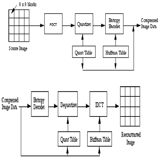
| In 1992, the Joint Photographic Experts Group (JPEG) established the first international standard for still image compression where the encoders and decoders are Discrete Cosine Transform (DCT) – based [1]. The JPEG standard specifies three modes namely sequential, progressive, and hierarchical for lossy encoding, and one mode of lossless encoding. The DCT –based encoder worked by segmentating the image into 8*8 blocks. Each block makes its way through each processing step, and yields output in compressed form into the data stream. As image pixels are highly correlated, the DCT achieves data compression by concentrating most of the signal in the lower spatial frequencies. For a typical 8*8 sample block from a typical source image, most of the spatial frequencies have Zero or near – Zero amplitude and need not be encoded. In principle, the DCT introduces no loss to the source image samples; it transforms them to a domain in which they can be more efficientlyencoded. |
JPEG 2000: DWT BASED IMAGE COMPRESSION STANDARD
|
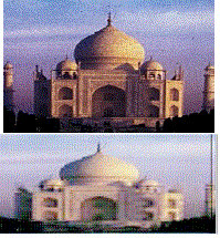
| Over the Past several years, the wavelet transform has gained widespread acceptance in signal processing in general and in image compression research in particular. In many applications wavelet – based schemes outperform other coding schemes like those that the one based on DCT [2]. Despite all the advantages of JPEG compression schemes based on DCT namely simplicity, satisfactory performance, and availability of special purpose hardware for implementation these are not without their shortcomings. Since the input image needs to be ‘blocked’, correlation across the block boundaries is not eliminated. This results in noticeable and annoying “blocking artifacts” particularly at low bit rates as shown in figure 3(a). Since there is no need to block the input image and its basis functions have variable length, wavelet- based coding is more robust under transmission and decoding errors, and facilitates progressive transmission of images. In addition, they are better matched to the HVS characteristics. Because of their inherent multire solution nature, wavelet coding schemes are especially suitable for applications where scalability and tolerable degradations are important. |
| JPEG 2000 is a wavelet based image compression standard. It was created by the JPEG committee with the intention of superseding their original discrete cosine transform based JPEG standard. JPEG 2000 can operate at higher compression ratios without generating the characteristic ‘blocky and blurry’ artifacts of the original DCT – based JPEG standard. This standard will include many modern features including improved low bit–rate compression performance, lossless and lossy compression, continuous –tone and bi-level compression, compression of large images, single decompression architecture, transmission in noisy environments including robustness to bit – errors, progressive transmission by pixel accuracy and resolution, content- based description, and protective image security [18]. |
PERFORMANCE COMPARISON: DCT VS. DWT
|
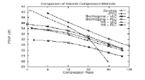
| A final word on the performance of wavelet–based and JPEG coders. The peak signal to noise (PSNR) of several different wavelet compression techniques applied to the 512 x 512, 8–bpp Taj image as well as the performance of a baseline JPEG image compressor are compared and are reproduced in figure 4. It is seen that, at compression ratios less than 25:1 or so, the JPEG performs better numerically than the simple wavelet coders. At compression ratios above 30:1, JPEG performance rapidly deteriorates, while wavelet coders degrade gracefully well beyond rations of 100:1 |
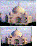
| The graphs also that both the encoding technique and the particular wavelet used can make a significant difference in the performance of a compression system: the zero tree coder performs the best: biorthogonal perform better than W6: and variance; length coders (VLC) perform better than fixed length coders (FLC). A comparison of color real images are shown in Figure 4. The left image has been compressed using DWT compression standard and the right image has been compressed using standard JPEG [10]. Both images have compression ratio of 100:1. |
ADVANTAGES
|
| There are several claimed advantages of JPEG2000 over the ordinary JPEG standard |
| • Superior compression performance |
| At high bit rates, where artifacts become nearly imperceptible, JPEG 2000 has a compression advantage over JPEG by roughly 20% on average. At lower bit rates, JPEG 200 has a much more significant advantage over certain modes of JPEG The compression gains over JPEG are attributed to the use of DWT and a more sophisticated entropy encoding scheme. |
| • Multiple resolution representation |
| JPEG200 provides seamless compression of multiple image components, with each component carrying from 1to 16 bits per component sample. With tiling, it handles images of arbitrary large size in a single code stream. |
| • Progressive transmission by pixel and resolution accuracy, commonly referred to as progressive decoding and signal – to – noise ratio (SNR) scalability JPEG200 Provides efficient code stream organizations which are progressive by pixel accuracy, by quality (SNR), by resolution or by size. |
| • Lossless and lossy compression |
| JPEG2000 provides both lossless and lossy compression in a single compression architecture. Lossless compression is provided by the use of a reversible (integer) wavelet transform. |
| • Random code stream access and processing also referred as Region of Interest (ROI) |
| JPEG2000 code streams offer several mechanisms to support spatial random access or region of interest at varying degrees of granularity. |
| • Error resilience |
| JPEG200is robust to bit errors introduced by noisy communication channels. This is accomplished by the inclusion of resynchronization markers, blocks, and the provision of mechanisms to detect and conceal errors within each block. |
| • Sequential buildup capability |
| JPEG200 allows for encoding of an image from top to bottom in a sequential fashion without the need to buffer an entire image. |
WAVELETS IN IMAGE COMPRESSION
|
| Wavelets are mathematical functions that cut up data into different frequency components, and then study each component with a resolution matched to its scale. They have advantages over traditional Fourier methods in analyzing physical situations where the signal contains discontinuities and sharp spikes. Wavelet was developed independently in the fields of mathematics, quantum physics, electrical engineering, and seismic geology. Interchanges between these fields during the last ten years have led to may new wavelet applications such as image compression, turbulence, human vision, radar, and earthquake prediction. Wavelet theory uses a two - dimensional expansion set to characterize and give a time - frequency localization of a one - dimensional signal. Founded on the same principles of Fourier theory, the wavelet transform calculates inner products of signal with a set of basis functions to find coefficients that represent the signal. Since this is a linear system, the signal can be reconstructed by a weighted sum of the basis function. In contrast to the one-dimensional Fourier basis localized in only frequency, the wavelet basis is twodimensional – localized in both frequency and time. A signal's energy, therefore, is usually well represented by just a few wavelet expansion coefficients. |
DISCRETE WAVELET TRANSFORM
|
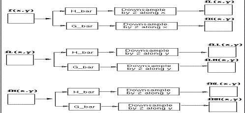
| The Discrete Wavelet Transform can be described as a series of filtering and sub sampling. In each level in this series, a set of 2j-1 coefficients are calculated, where j ?J is the scale and N = 2 J is the number of samples in the input signal. The coefficients are calculated by applying a high - pass wavelet filter to the signal and down sampling the result by a factor of 2. At the same level, a low - pass scale filtering is also performed (followed by down - sampling) to produce the signal for the next level. Both the wavelet and scale filters can be obtained from a single Quadrature Mirror Filter (QMF) function that defines the wavelet. Each set of scale - coefficient corresponds to a "smoothing" of the signal and the removal of details, whereas the wavelet - coefficients correspond to the "differences" between the scales. Wavelet theory shows that from the coarsest scale - coefficients and the series of the wavelet - coefficients the original signal can be reconstructed. The total number of coefficients (scale + wavelet) equals the number of samples in the signal. It is given by the formula as, |
 |
| An important feature of DWT is the fact that the transform can be implemented using appropriately designed quadrature mirror filters (QMFs) A QMF consists a pair of high - pass and low - pass filters. With each application of the filter, the original signal is successively decomposed into components of lower resolution, while the high frequency components are not analyzed any further. Using this approach, and efficient construction of forward and reverse DWTs can be implemented in o(n). |
TRANSLATION AND SCALING
|
| As the index k changes, the location and scaling of the wavelet moves along the time axis. As the index j changes, the shape of the wavelet changes in scale. As the scale becomes finer (j larger), the time steps become smaller. Both the narrower wavelet and the smaller steps allow a representation of greater detail resolution. |
| A. The Scaling Function |
| In order to use the idea of multiresolution, a scaling function f (t) is used to define the wavelet function. |
 |
| A two - dimensional family of functions is generated from the basic scaling function by scaling and translation |
 |
| The spans of the various scaling functions are nested, and after some linear algebra, the recursive scaling function can be rewritten as: |
 |
| Where the coefficients h(n) are a sequence of real or complex numbers called the scaling function coefficients and the root two maintains the norm of the scaling function. The wavelet function can then be represented by a weighted sum of shifted scaling functions |
 |
| for some set of coefficients h1(n). |
| B. Displaying the DWT |
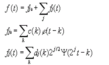
| There are five displays that show the various characteristics of the DWT well:Time - domain. This, however, gives no information about frequency or scale. Three - dimensional plot c(k) and dj(k) over the j, plane.Time functions fj(t) at each scale by summing over k so that |
 |
| C.Subband Coding |
| The fundamental concept behind Subband Coding (SBC) is to split up the frequency band of a signal (image in our case) and them to code each sub band using a coder and bit rate accurately matched to the statistics of the band. SBC has been used extensively first in speech coding and later in image coding because of its inherent advantages namely variable bit assignment among the sub bands as well as coding error confinement within the sub bands. |
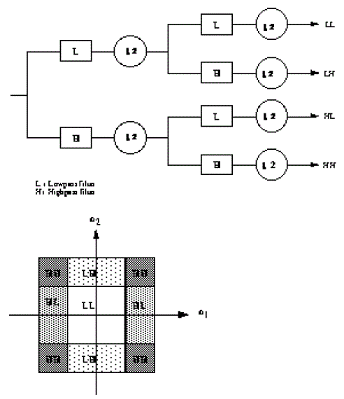
| Woods and O'Neil used a separable combination of one - dimensional Quadrature Mirror Filter banks (QMF) to perform a 4-band decomposition by the row - column approach as shown in figure 6(a). Corresponding division of he frequency spectrum is shown in figure 6(b). The process can be iterated to obtain higher band decomposition filter trees. At the decoder, the sub band signals are decoded, up sampled and passed through a bank of synthesis filters and properly summed up to yield the reconstructed image. |
| D. From Sub band to Wavelet Coding |
| Over the years, there have been many efforts leading to improved and efficient design of filter banks and sub band coding techniques. Since 1990, methods very similar and closely related to sub band coding have been proposed by various researchers under the name of Wavelet Coding (WC) using filters specifically designed for this purpose. Such filters must meet additional and often conflicting requirements. These include short impulse response of the analysis filters to preserve the localization of image features as well as to have fast computation, short impulse response of the synthesis filters to prevent spreading of artifacts (ringing around edges) resulting from quantization errors, and linear phase of both types of filters since nonlinear phase introduce unpleasant waveform distortions around edges. Orthogonally is another useful requirement since orthogonal filters, in addition to preservation of energy, implement a unitary a unitary transform between the input and the sub bands. But, as in the case of 1-D, in two - band Finite Impulse Response (FIR) systems linear phase and orthogonally are mutually exclusive, and so orthogonally is sacrificed to achieve linear phase. |
| E. Link between Wavelet Transform and Filter bank |
| Construction of orthonormal families of wavelet basis functions can be carried out in continuous time. However, the same can also be derived by starting from discrete-time filters. Daubechies was the first to discover that the discrete-time filters or QMFs can be iterated and under certain regularity conditions will lead to continuous - time wavelets. This is a very practical and extremely useful wavelet decomposition scheme, since FIR discrete-time filters can be used to implement them. It follows that the orthonormal bases in Daubechies correspond to a sub band-coding scheme with exact reconstruction property, using the same FIR filters for reconstruction as for decomposition. Therefore, sub band coding developed earlier is in fact a form of wavelet coding in disguise. |
| F. An Example of Wavelet Decomposition |
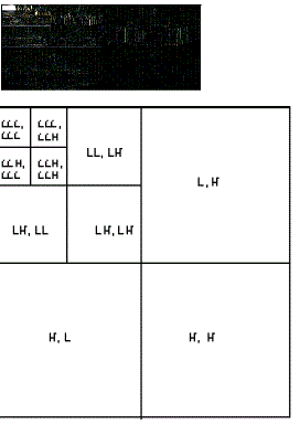
| There are several ways wavelet transforms can decompose a signal into various sub bands. These include uniform decomposition, octave - band decomposition, and adaptive or wavelet - packet decomposition. Out of these, octave - band decomposition is the most widely used. This is a non-uniform band splitting method that decomposes the lower frequency part into narrower bands and the high - pass output at each level is left without any further decomposition. Figure 7(a) shows the various sub band images of a 3-level octave - band decomposed Taj using the popular CDF-9/7 biorthogonal wavelet. |
| The choice of optimal wavelet function in an image compression system for different image types can be provided in a few steps. For each filter order in each wavelet family, the optimal number of decompositions can be found. The optimal number of decompositions gives the highest RSNR values in the wide range of compression rations for a given filter order. For lower filter orders, better results are reached with more decompositions than for higher filter orders. The shaded areas in Table show the optimal number of decompositions for a given filter order, while bold type mark the optimal combination of filter order and number of decompositions for image Taj (5 decompositions, filter order 5) |
COMPRESSION METHODOLOGIES
|
| The steps involved in the compression process are outlined below. |
| A. Digitization |
| The first step in the wavelet compression process is to digitize the image. The digitized image can be characterized by its intensity levels, or scales of gray which range from 0 (black) to 255 (white), and its resolution, or how pixels per square inch may. Each of the bits involved in creating an image takes up both time and money, so a tradeoff must be made. |
| B. Thresholding |
| In certain signals, many of the wavelet coefficients are close or equal to zero. Through a method called thresholding, these coefficients may be modified so that the sequence of wavelet coefficients contains long strings of zeros. Through a type of compression known as entropy coding [21], these long strings may be stored and sent electronically in much less space. There are different types of thresholding. In hard shareholding, a tolerance is selected. Any wavelet whose absolute value falls below the tolerance is set to zero with the goal to introduce many zeros without losing a great amount of detail. There is not a straightforward easy way to choose the threshold, although the larger the threshold that is chosen the more error that is introduced into the process. Another type of thresholding is soft thresholding. Once again a tolerance, h, is selected. If the absolute value of an entry is less than the tolerance, than that entry is set to zero. All other entries, d, are replaced with sign(d)??d? - h?. Soft thresholding can be thought of as a translation of the signal toward zero by the amount h. A third type of thresholding is quantile thresholding. In this method a percentage p of entries to be eliminated are selected. The smallest (in absolute value) percent of entries are set to zero. |
C. Entropy Coding
|
| Wavelets and thresholding help process the signal, but up until this point, no compression has yet occurred. Once method to compress the data is Huffman entropy coding. With this method, and integer sequence, q, is changed into a shorter sequence, e, with the numbers in e being 8 bit integers. The conversion is made by an entropy coding table. Strings of zeros are coded by the numbers 1 through 100, 105, and 106, while the non - zero integers in q are coded by 101 through 104 and 107 through 254. In Huffman entropy coding, the idea is to use two or three numbers for coding, with the first being a signal that a large number or long zero sequence is coming. Entropy coding is designed so that the numbers that are expected to appear the most often in q, need the least amount of space in e. |
D. Quantization
|
| The fourth step of the process, known as quantization, converts a sequence of floating numbers w' to a sequence of integers q. The simplest form is to round to the nearest integer. Another option is to multiply each number in w' by a constant k, and then round to the nearest integer. Quantization is called lossy because it introduces errors into the process, since the conversion of w' to q is not a one - to - one function. Daubechies Wavelets In order to process an image, symmetric biorthogonal wavelets is used. These have two father and two mother wavelets, and are required in order to compress a matrix of data. The Daubechies wavelet family is the most widely used wavelet for image compression, with six coefficients and biorthogonality. But in study, Deslauriers set of wavelets are used for the transformation of the image. Deslauriers wavelets are also symmetric biorthogonal wavelets. |
IMPLEMENTATION
|
| The experiment presented in this paper compress a natural grayscale image of TAJ using a standard MATLAB wavelet code package, WAVELAB 802, to perform the transforms. The wavelets chose to use were the Deslauriers wavelets of polynomial size 3 [15]. |
| Wavelab is nothing but a library of MATLAB 6.0 routines for wavelet analysis, wavelet - packet analysis, cosine - packet analysis and matching pursuit. The compression scheme used was to set a threshold value that was some fraction of the norm of the entire wavelet transform matrix. If the magnitude of a wavelet in the representation was not larger than this value, it was not included in the compression. Then rebuilt an image, which (to some degree that depended on how many bases we included) resembled the original image by running the inverse transform. |
| Short for "matrix laboratory", MATLAB was invented in the late 1970s by Cleve Moler, the chairman of the computer science department at the University of New Mexico. MATLAB is a high - level technical computing language and interactive environment for algorithm development, matrix manipulation, data visualization, data analysis, and numeric computation. |
PROCEDURE
|
| load / home/ nirav / elec 301/Taj 256.mat; |
| imagesc (Taj 256); |
| colormap (gray (2560); |
| [qmf, dqmf] = MakeBSFilter ('Deslauriers', 3); |
| % The Make BSFilter function creates biorthonormal filter pairs. The f |
| % Pairs that we're making is an Interpolating (Deslauriers-Dubuc) filter |
| % of polynomial degree 3 |
| w/c = FWT2 _PB(1ena 256, qmf, dqmf); |
| % wc correspond to the wavelet coefficients of the sample image % FWT2_PB is a function that takes a 2 dimensional wavelet transform % We specify the image matrix, the level of coarseness (1), the quadrature % mirror filter (qmf), and the dual quadrature mirror filter (dqmf)n1 = norm (taj256) / (4*norm (size (taj 256)));% if the value of the wavelet coefficient matrix at a particular % row and column is less than the tolerance, we 'throw' it out % and increment the zero count. |
| zerocount = 0; |
| for i = 1:256 |
| for j = 1: 256 |
| if (abs(wc(i,j)) <nl) |
| wc(i,j) = 0; |
| zerocount = zerocount +1; |
| end |
| end |
| end |
| x = IWT2 _PV (wc, i, qmf, dqmf); |
| imagesc(x); |
| %here is some sample code to view how these deslauriers wavelets look |
| [qmf, dqmf] = Make BSFilter ('Deslauriers', 3); |
| for i = 1:256 |
| for j = 1: 256 |
| wc(i,j) = 0; |
| end |
| end |
| % this is the Deslauriers(4,2) matrix |
| wc (4,2) = 1000 |
| x = IWT2_PB(wc, 1, qmf, dqmf); |
| imagesc(x); |
RESULTS
|
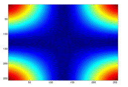
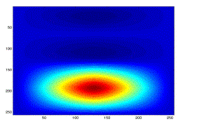
| These are some basis vectors obtained by running the inverse wavelet transform on a matrix with a single nonzero value in it. |
| Taj, one of the most common test images in compression research, consists primarily of low frequency content. The figures below show the original image of Taj and the compressed image for the different thresholding values. |
CONCLUSION
|
| Considering the goal was to come up with a way to compress an image using wavelets, this thesis succeeded in representing an image using symmetric, biorthogonal wavelets, applied some sort of thresholding to the wavelet representation, and took the inverse. It subjectively compared the results from the compression algorithm to explore the tradeoffs between including more bases in the compressed image, and the compression ratio. |
| Ways that could improve upon this work included: |
| • Determining a better quantization scheme |
| • Comparing soft thresholding to our own thresholding technique |
| • Calculating the resulting energy in the compressed image to quantify the success of a set of parameters for compression |
Tables at a glance
|
 |
 |
 |
 |
 |
| Table 1 |
Table 2 |
Table 3 |
Table 4 |
Table 5 |
|
| |
Figures at a glance
|
 |
 |
 |
 |
 |
| Figure 1 |
Figure 2 |
Figure 3 |
Figure 4 |
Figure 5 |
|
 |
 |
 |
 |
 |
| Figure 6 |
Figure 7 |
Figure 8 |
Figure 9 |
Figure 10 |
|
References
|
- G.M. Davis, A. Nosratinia. Wavelet-based Image Coding: An Overview. Applied and Computational Control, Signals and Circuits, Vol. 1,No. 1,1998.
- S. Mallat. A Wavelet Tour of Signal Processing. Academic Press, New York, NY, 1998.
- M. Antonini, M. Barlaud, P. Mathieu, I. Daubechies. Image coding using wavelet transform. IEEE Trans. Image Proc., Vol. 5, No. 1, pp.205-220,1992.
- J.M. Shapiro. Embedded image coding using zerotrees of wavelet coefficients. IEEE Trans. Signal Proc., Vol. 41, No. 12, pp. 3445{3462,1993.
- Said, W.A. Pearlman. Image compression using the spatial-orientation tree. IEEE Int. Symp. on Circuits and Systems, Chicago, IL, pp.279{282,1993.
- Said, W.A. Pearlman. A new, fast, and e_cient image codec based on set partitioning in hierarchical trees. IEEE Trans. on Circuits andSystems for Video Technology, Vol. 6, No. 3, pp. 243{250, 1996.
- Said, W.A. Pearlman. An image multi-resolution representation for loss-less and lossy image compression. IEEE Trans. Image Proc.,Vol. 5, No. 9,pp. 1303{1310, 1996.
- G.K. Wallace. The JPEG still picture compression standard. Comm. of the ACM, Vol. 34, No. 4, pp. 30{44, 1991.
- J. Tian, R.O. Wells, Jr. A lossy image codec based on index coding. IEEE Data Compression Conference, DCC '96, page 456, 1996.
- J. Tian, R.O. Wells, Jr. Embedded image coding using wavelet-di_erence-reduction. Wavelet Image and Video Compression, P. Topiwala,
- ed.,pp. 289{301. Kluwer Academic Publ., Norwell, MA, 1998.
- J. Tian, R.O. Wells, Jr. Image data processing in the compressed waveletdomain. 3rd International Conference on Signal Processing Proc.,B. Yuan and X. Tang, Eds., pp. 978{981, Beijing, China, 1996.
- Witten, R. Neal, J. Cleary. Arithmetic coding for data compression. Comm. of the ACM, Vol. 30, No. 6, pp. 1278{1288, 1986.
- WDR and ASWDR compressors are part of the FAWAV software packageat ttp://www.crcpress.com/edp/download/fawav/fawav.htm/3653, Visual Communications and Image Processing '99, San Jose, CA,Jan. 1999.
- J.S. Walker. A lossy image codec based on adaptively scanned wavelet difference reduction. Submitted to Optical Engineering.
- R.W. Buccigrossi, E.P. Simoncelli, Image compression via joint statistical characterization in the wavelet domain. IEEE Trans. on Image Proc.,Vol. 8, No. 12, 1999.
- A.R. Calderbank, I. Daubechies, W. Sweldens, B.-L. Yeo, Wavelet transforms that map integers to integers. Applied and ComputationalHarmonic Analysis, Vol. 5, No. 3, pp. 332-369, 1998.
- J.C. Russ, The Image Processing Handbook. CRC Press, Boca Raton, FL,1995.
- H. Malvar, Progressive wavelet coding of images. Proc. of IEEE Data Compression Conference, Salt Lake City, UT, pp. 336{343, March, 1999.
- J. Li, S. Lei, An embedded still image coder with rate-distortion optimization. IEEE Trans. on Image Proc., Vol. 8, mno. 7, pp. 913{924, 1999.
|