International Journal of Advanced Research in Electrical, Electronics and Instrumentation Engineering
ISSN ONLINE(2278-8875) PRINT (2320-3765)
ISSN ONLINE(2278-8875) PRINT (2320-3765)
Sara Asheer1, Amna Al-Marwani1, Tamer Khattab2, Ahmed Massoud3
|
| Related article at Pubmed, Scholar Google |
Visit for more related articles at International Journal of Advanced Research in Electrical, Electronics and Instrumentation Engineering
This paper discusses the use of contactless power and data transfer (CPDT) for charging electric vehicles (EV). The main contribution of this paper spans the analysis and development of the contactless power transfer (CPT) design, along with the practical implementation of the system prototype. The CPT system consists mainly of two parts; the transmitter and the receiver part. At the transmitter part there is a DC supply to supply power to the system. Then this DC will be converted to AC of high frequency through an inverter. Single-phase full bridge inverter is employed for this application. The AC voltage resulting from the inverter will be transferred through a coil from the transmitter side to the receiver side. This is achieved through a series resonant circuit in the transmitter and the receiver ends. After transferring the power to the secondary side of the system, it is used to charge the battery of the electric vehicle. Therefore a rectifier is needed to convert the AC to DC voltage. Data also is transferred wirelessly with the power in order to control the charging process for the electric vehicles with different proposed scenarios. A scaled down prototype has been tested experimentally for the CPDT. Despite tested for different air gaps, the implemented CPT system results are presented for an air gap of 1 cm.
Keywords |
||||||||||||||||||||||||||
| Contactless power transfer, data transfer, Electric vehicles, Resonant converter. | ||||||||||||||||||||||||||
INTRODUCTION |
||||||||||||||||||||||||||
| Electric vehicles have received a wide range of acceptance in the recent years as an emerging technology. Its market increases dramatically as it does not produce harmful gases as fuel-based vehicles do. Electric vehicles depend on electricity to charge batteries where renewable energy resources as solar energy and wind energy, represent a great advantage [1-3]. In order to charge electric vehicles there is a need to have a wire attached to the battery of the car that can be connected to the plug. The main disadvantage of this system is that the connection should be achieved manually. This method is not very convenient and might have safety risks in wet condition. Therefore a suitable solution for that is to wirelessly transfer the power to the electric vehicles which is called contactless power transfer (CPT). | ||||||||||||||||||||||||||
| CPT is the process in which electrical energy is transferred between two or more electrical devices without using direct conducting wire connections [4]. It is a new way to supply electrical devices with energy without the use of cables or connectors, which increases the reliability due to maintenance-free operation of such important system [5]. This system could be used in low power devices such as home devices and offices, as well as high power devices such as aerospace, biomedical, and robotics applications [6]. The advantages of this technology are; maintenance-free operation, no sparking effects due to contact problems, complete electric isolation between primary and secondary conductors and ruggedness against dust and environmental conditions [7]. CPT provides a higher level of safety and more flexibility to meet constraints on space or other constraints. CPT is achieved through a suitable type of waves, which carries the energy. CPT system can transfer energy through photonic light waves, electric or magnetic fields in electromagnetic waves [8]. CPT systems can be categorized into capacitive coupling and inductive coupling. Capacitive coupling is used for low power range, while inductive coupling allows the transfer of power in the range between mill watts to kilowatts [9]. Some of the advantages of capacitive power transfer is that using capacitor make the system simpler, have low cost, low electromagnetic radiation, and no need for magnetic flux guiding and shielding components [9]. Although this system has many advantages but it also has some constraints that limit the performance of the system. The amount of coupling capacitance depends on the available area of the device. This can be solved by either increasing the size of the capacitor, which is not practical in some applications, or by targeting low power applications [10,11]. The inductive power transfer is widely used and has many advantages such as its ability to transfer larger power than capacitive coupling. Inductive power transfer carries lower risk of electric shock because there are no exposed conductors. Moreover, inductive power transfer is waterproof since the charging connections are fully enclosed, which makes it suitable for harsh environments in general. In this paper, CPT will refer to inductive power transfer. The main disadvantages of CPT are heat and power transfer efficiency [12,13]. It takes more power to inductively charge an energy storage system than charging it through normal conductive means. This is due to the higher power loss in the induction coils. | ||||||||||||||||||||||||||
| This paper discusses the use of contactless power and data transfer (CPDT) technology for charging electric vehicles (EV). The main contribution of this paper spans the analysis and developments of the CPT design, along with the practical implementation of the system prototype. The CPT system consists mainly of two parts; the transmitter and the receiver part. At the transmitter part there is a DC supply to supply power to the system. Then this DC will be converted to AC of high frequency through an inverter. Single-phase full bridge inverter is employed for this application. The AC voltage resulting from the inverter will be transferred through a coil from the transmitter side to the receiver side. This is achieved through a series resonant circuit in the transmitter and the receiver ends. After transferring the power to the secondary side of the system, it is used to charge the battery of the electric vehicle. Therefore a rectifier is needed to convert the AC to DC voltage. Data also is transferred wirelessly with the power in order to control the charging process for the electric vehicles with different proposed scenarios. A scaled down prototype has been tested experimentally for the CPDT. Despite tested for different air gaps, the implemented CPT system results are presented for an air gap of 1 cm. By having the transmitter section of the charging system built in at the parking slot, the chances of danger or harmfulness on anyone that enter the parking space are reduced. To make sure that the CPT system will only transfer power when a car is on top of it, proximity switches can be used to detect that the car is parked correctly in the parking slot, then the CPT system will start charging. Different charging scenarios; charging once parked (COP), charging based on request (CBR), charging based on request with delay (CBRD), and charging with switched OFF engine (CEOFF) are proposed. | ||||||||||||||||||||||||||
CONTACTLESS POWER TRANSFER SYSTEM |
||||||||||||||||||||||||||
| This section discusses the CPT by inductive coupling. It explores the CPT transformer concept then it investigates the resonant circuits, which are mainly four types (based on the resonant circuit); series-series (SS), series-parallel (SP), parallel-series (PS), and parallel (PP). Following the comparison between the four topologies, the choice of the topology used in the CPT system is discussed. Then the role of the communication system in this design will be explored. The CPT system consists of two parts; the transmitter side and the receiver side. In the transmitter side, the DC supply will be converted to AC through an inverter (operated at a reasonably high frequency) with a resonant circuit. Then through the inductive coupling to the receiver side of the system. On the receiver side the AC power will be converted to DC using a rectifier. The system does not only transfer power, it also transfers data between transmitter and receiver sides. The data transmission system will be achieved through a separate system than the power transfer system; as high power is being transferred which may affect the data transfer. The overall system is presented in Fig. 1 [3]. | ||||||||||||||||||||||||||
A. Single phase inverter |
||||||||||||||||||||||||||
| Fig. 2 shows the power circuit diagram of a single-phase full-bridge voltage source inverter. In order to produce a high frequency output, the inverter will be controlled for square wave operation as shown in Fig. 2. | ||||||||||||||||||||||||||
B. Resonant circuits |
||||||||||||||||||||||||||
| Resonant circuit is the second part of the CPT system as shown in Fig. 1. Capacitors are inserted in both ends in order to cancel the effect of the high leakage inductances of the transmitter and receiver coils. The leakage inductance is high due to the distance separating both coils and/or air core. The possible combination of the resonant circuits in the transmitter and receiver circuit can be classified based on the connection of the capacitor. The resonant circuit has four types, each type represented by two letters S for series and P for parallel, the first letter represents the transmitter side and the second part represents the receiver side. The choice of the SS topology has two main advantages that make it beneficial. Firstly, the reflected impedance of the secondary winding on to the primary winding has only a real reflected component and no reactive component [13]. The second advantage is that the choice of primary and secondary compensation capacitances is independent of either mutual inductance or the load (i.e. the primary and secondary resonance frequencies are independent of either the mutual inductance or the load and only depend on the selfinductance of the primary and secondary windings and their respective compensation capacitances) [13]. | ||||||||||||||||||||||||||
COMMUNICATION SYSTEM |
||||||||||||||||||||||||||
| In the CPDT system, the second part is the communication system that goes in parallel with the power transfer system. This part is an important part of the CPT as it initiates the command for the system to start charging and it also gives the command to stop charging. | ||||||||||||||||||||||||||
A. ZigBee for the communication system |
||||||||||||||||||||||||||
| In the data transmission system that is being designed the ZigBee program is being used [14,15]. ZigBee is often used to transmit data over long distances, passing through intermediate devices to reach more distant ones. Moreover, ZigBee networks are able to reach all devices without central control or high-power transmitter receiver [16]. Also, ZigBee is used for applications that need a secured network with a low data rate and a long battery life. It is best suited for applications that include wireless light switches, traffic management systems, electrical meters within home displays, and other applications that require a short-range wireless transfer of data at low rates. ZigBee is a low-cost, low-power standard [17]. Also ZigBee nodes can change modes such as from sleep to active mode in 30ms or less, that shows that the delay can be low and the devices can respond faster than Bluetooth which takes around three seconds to activate. ZigBee has another advantage that is the average consumed power can be low which will result in a longer lifespan for the battery that is due to the ZigBee nodes that can sleep most of the time. Therefore ZigBee has been employed in the communication system. | ||||||||||||||||||||||||||
B. Power Transfer |
||||||||||||||||||||||||||
| First of all when the receiver is in the range of the transmitter, the transmitter will send a notification to the controller of the receiver asking to check the battery level. If the battery is low it will start charging and if the battery is full then it will stop charging. This operation will keep on going as long as the receiver is in the range of the transmitter. Different scenarios for the charging methods will be discussed in the next section. | ||||||||||||||||||||||||||
PRACTICAL IMPLEMENTATION OF THE SYSTEM |
||||||||||||||||||||||||||
| The practical implementation of the system and the description of the approach to measure the inductances of the CPT system are discussed in this section. | ||||||||||||||||||||||||||
A. System description |
||||||||||||||||||||||||||
| The contactless power and data transfer system is shown in Fig. 3. Each block of the system is explained in the following subsections. Fig. 4 presents the system test rig ad the inverter is detailed in Fig. 5. The employed digital signal processor is ezdsp TMS320F28335. Features of the DSP TMS320F28335 are, 30 MHz input clock, 150 MHz operating speed, up to 18 PWM Outputs, and 12-Bit ADC (16 Channels). | ||||||||||||||||||||||||||
B. SS resonant topology |
||||||||||||||||||||||||||
| The SS resonant topology consists of an inductor and a capacitor on each side of the system. The two sides inductors are shown in Fig. 6. It was made of wire with 30 turns for both sides. The separation between the two windings has been set to 1cm. Therefore to conduct different tests at different parameters it is more convenient to use variable capacitors. | ||||||||||||||||||||||||||
C. Measurement of mutual and leakage inductances |
||||||||||||||||||||||||||
| Two approaches have been used for the measurement of the mutual and leakage inductances; direct measurement and series connection. The following subsections clarify the two approaches. | ||||||||||||||||||||||||||
C.1. Approach 1: Direct measurement |
||||||||||||||||||||||||||
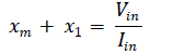
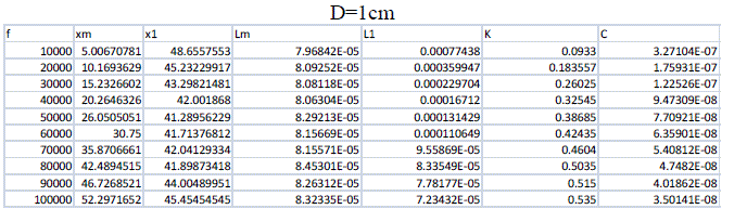
| Function generator was used to supply a voltage at a frequency of 30 kHz (the frequency of interest) to the primary coil. Then the primary current and the secondary voltage are measured while the secondary is open (the primary no load current and secondary no load voltage). These results yield the magnetizing inductance and leakage inductance. From equations (1) and (2), the value of the leakage and mutual impedance is calculated. To find the value of the capacitor, equations (3) and (4) are used. Appendix A contains the table of values for the leakage and mutual impedances for different separating distances and frequencies. | ||||||||||||||||||||||||||
 |
||||||||||||||||||||||||||
C.2. Approach 2: Series connection |
||||||||||||||||||||||||||
| Another test was used to measure the leakage inductance and the mutual inductance. The two inductors are connected in series with the two possible polarities for the mutual coupling as shown Fig. 7). The result of the two measurements Lx1 and Lx2 are as follows: | ||||||||||||||||||||||||||
| Then from (5) and (6), the mutual inductance can be obtained. Also the leakage inductances L1 and L2 will be assumed equal (the same number of turns). | ||||||||||||||||||||||||||
| The CPT System parameters, with the leakage and mutual inductances found from the test results, can be enumerated as shown in table 1. | ||||||||||||||||||||||||||
D. Communication system |
||||||||||||||||||||||||||
| For the start and stop of the charging process, a wireless communication system is used. The communication system consists of two waspmote boards [18] connected with two Zigbee modules. The baud rate of the system is 38400 and the distance between the transmitter and receiver can be small or large because the waspmote uses Zigbee which has a large distance of communication. The power required for the waspmote to operate is low. It consumes 62μA in the mode that was used in this design. In theory, the power transfer system and data transfer system should be placed far from each other so that there will not be any interference between the transmitted data and the transmitted power. But because the data communication system can transfer data up to 2.4GHz while the power is transferred at 30kHz, the interference will be very small and can be neglected. Therefor the data communication system was placed near the power transfer system. Fig. 1 is the block diagram that shows the location of the data transfer system. There is more than one scenario in which the communication system is used. These scenarios are discussed below. | ||||||||||||||||||||||||||
| The first scenario is by using two waspmote boards. One waspmote board is connected to the DSP of the inverter in the power transmitter part of the system. The other waspmote board is connected to the battery at the power receiver part of the system. At the power receiver part, the waspmote will be connected to a current sensor. This current sensor will sense the flow of the current in the battery of the electric vehicle and accordingly will send a message to the transmitter part waspmote to either start charging or stop charging. | ||||||||||||||||||||||||||
| The second scenario is by using one-waspmote board. This waspmote board will be connected to the power transmitter side of the system. This board will sense the light; therefore if a car is parked on top of the board which will send for the system to start charging. Then a timer will also start. This timer is programmed to stop charging the battery after a certain time. This time is calculated for fully charging a dead battery. This method is not very efficient, if the battery was half charged or in any other state of level, the system will keep on charging even after the battery is fully loaded. Also the light sensing method might not be very efficient, that is because most parking has shading on top of them, which will make the light sensing operation tricky. | ||||||||||||||||||||||||||
| The third scenario is by using two waspmote boards. One waspmote board will be connected to the power transmitter side of the system; the other waspmote board will be connected to a button and will be placed according to the user in the range of the first waspmote board. When the user would like to start charging, the button will be pressed. Then the waspmote board connected to the button will send a message to the waspmote board connected to the power transmitter part will make the system start charging. To stop the charging process another button should be pressed. The stopping method of this scenario is not efficient. | ||||||||||||||||||||||||||
| The fourth scenario is the same as the third scenario but the stopping method is different. To stop the charging there will be a timer that is programmed according to the time it takes for a dead battery to fully charge. This method might be more efficient that the third method in a way that if the user forgot to stop charging, then the system will continue charging. But by having a timer even if the battery was not dead after a certain time the charging operation will stop. | ||||||||||||||||||||||||||
RESULTS AND DISCUSSIONS OF THE IMPLEMENTATION |
||||||||||||||||||||||||||
| This section discusses the results of the entire system. | ||||||||||||||||||||||||||
| A. The leakage and mutual inductances and impedances | ||||||||||||||||||||||||||
| Fig. 8 represents the mutual impedance, leakage impedance, mutual inductance, and leakage inductance for different distances between the primary coil and the secondary coil. In the figure below, it can be shown that when the frequency increases the leakage inductance decreases and mutual inductance increases. The mutual inductance is related to the coupling coefficient with the relationship shown in equation (7). | ||||||||||||||||||||||||||
| where k is the coupling coefficient and 0 ≤ k ≤ 1, L1 is the inductance of the first coil, and L2 is the inductance of the second coil. | ||||||||||||||||||||||||||
| The coupling coefficient is always between 1 and 0, “1” expresses perfect coupling. “0” expresses a system, where transmitter and receiver coils are independent of each other. Fig. 9 shows the relation between the frequency and the coupling factor for the different distance. It can be shown that as the frequency increases the coupling factor increases and when the distance increases the range of variation of the coupling factor decreases. | ||||||||||||||||||||||||||
B. Output results of the entire system |
||||||||||||||||||||||||||
B.1 The input voltage and current |
||||||||||||||||||||||||||
| Fig. 10 below shows the behavior of the input voltage and the input current of the resonant circuit for different value of resistive loads. In Fig. 10, the blue square waveform represents the input voltage and the pink waveform represents the input current when the frequency equals 30 kHz. | ||||||||||||||||||||||||||
C. The output voltage and current |
||||||||||||||||||||||||||
| Fig. 11 below shows the behavior of the output voltage and the output current for different value of resistive loads. In Fig. 11, the blue square waveform represents the output voltage and the pink waveform represents the output current. To calculate the input power of the system, the input voltage of the DC supply is measured and the input DC current of the supply is also measured, then the input power is calculated as shown in (8). | ||||||||||||||||||||||||||
| The average output power is calculated by averaging the result of the output voltage and current product. Then to calculate the entire efficiency of the system, equation (9) is used. | ||||||||||||||||||||||||||
| The system efficiency has reached 77% at R=20Ω | ||||||||||||||||||||||||||
D. Charging scenarios |
||||||||||||||||||||||||||
| In this section, different scenarios are described for the charging scheme. There are different scenarios to start charging. | ||||||||||||||||||||||||||
D.1. Charge once parked (COP) |
||||||||||||||||||||||||||
| The user of the electric vehicle does not control this charging method. Once the vehicle is parked correctly in the parking slot, the charging system will communicate with the electric vehicles and will send a message to check the battery levels. If the battery needed charging then it will transfer the power. The charging system will keep on communicating with the electric vehicle until the battery is fully charged then it will stop transferring the power. | ||||||||||||||||||||||||||
D.2. Charge based on request (CBR) |
||||||||||||||||||||||||||
| In this method the car will be charged and stop charging depending on the request of the user so it is a controlled method, when the car is parked the user must choose to send a message to the charging system either to start charging or to stop. | ||||||||||||||||||||||||||
D.3. Charge based on request with delay (CBRD) |
||||||||||||||||||||||||||
| In this method, the car will charged with delay so when the car is parked the user order the communication system to start charging, the car will start charging after a given time. This method allows the electric vehicle system to cool a little before charging. | ||||||||||||||||||||||||||
D.4. Charge with engine switched off (CEOFF) |
||||||||||||||||||||||||||
| In this method, the car will park on the parking slot and then when the engine is OFF a message will be sent from the charger to check the battery levels and then to start charging if needed and to stop if fully charged. | ||||||||||||||||||||||||||
CONCLUSION |
||||||||||||||||||||||||||
| In this paper, a CPDT system using inductive coupling has been designed and implemented. CPT can be used in many applications but the implication discussed in this paper is a wireless electrical vehicle charger. Data also is transferred wirelessly with the power in order to control the charging process for the electric vehicles with different proposed scenarios. A scaled down prototype has been tested experimentally for the CPDT and has been tested for an air gap of 1 cm. An efficiency of 77% has been achieved. Different charging scenarios; charging once parked (COP), charging based on request (CBR), charging based on request with delay (CBRD), and charging with switched OFF engine (CEOFF) are proposed. | ||||||||||||||||||||||||||
ACKNOWLEDGMENT |
||||||||||||||||||||||||||
| This publication was made possible by UREP grant 12-082-2-035 from the Qatar National Research Fund (a member of QatarFoundation). The statements made herein are solely the responsibility of the authors. | ||||||||||||||||||||||||||
Tables at a glance |
||||||||||||||||||||||||||
|
||||||||||||||||||||||||||
Figures at a glance |
||||||||||||||||||||||||||
|
||||||||||||||||||||||||||
APPENDIX A: CALCULATIONS OF INDUCTANCES |
||||||||||||||||||||||||||
 |
||||||||||||||||||||||||||
 |
||||||||||||||||||||||||||
References |
||||||||||||||||||||||||||
|


