Keywords
|
| Solar, Photo voltaic (PV) array, Fuel Cell, Direct Quadrature (dq), Synchronous Reference Frame (SRF), Voltage Source Inverter (VSI). |
I. INTRODUCTION
|
| Nowadays, fossil fuel is the main energy supplier of the worldwide economy, but the recognition of it as being a major cause of environmental problems makes the mankind to look for alternative resources in power generation. Moreover, the day-by-day increasing demand for energy can create problems for the power distributors, like grid instability and even outages. The necessity of producing more energy combined with the interest in clean technologies yields in an increased development of distribution power systems using renewable energy. Renewable energy sources like wind, sun, and hydro are seen as a reliable alternative to the traditional energy sources such as oil, natural gas, or coal. The penetration of renewable and distributed energy sources is increasing exponentially all over in developed and developing countries. More stringent grid requirements imposed by utility operators are aimed in maintaining grid stability because of random nature of such non-dispatch able and dispersed small power plants. Distributed energy sources are connected to the grid through power converters which besides transferring the generated dc power to the ac grid should also be able to exhibit advanced functions like: dynamic control of active and reactive power, stationary operation within a range of voltage and frequency, voltage ride-through, reactive current injection during faults, participation in grid balancing act like primary frequency control, and so on. Therefore, all the reasons detailed above are supporting the motivation of this work, where a control of a grid-connected power electronic converter will be analysed in order to support further developments of renewable energy integration with the utility grid. This section details the background and literature on different types of renewable energy sources, approaches for voltage source inverter (VSI) control such as controls implemented in synchronous reference frame, rotating and natural reference frames along with grid synchronization possibilities for these control techniques.[1]presents a brief overview on renewable energy sources and detailed description on modelling a hybrid energy system in Matlab. Renewable energy is simple enough: the electricity we need every day, created by sources which are naturally replenished. Types of renewable energy include: wind, hydro and solar. All these things occur naturally without man-made intervention. Other, less common, forms of renewable energy include biomass, biofuel and anaerobic digestion. Fuel cells are a promising new technology for use as a source of heat and electricity for buildings, and as an electrical power source for electric motors propelling vehicles.As energy demands around the world increase, the need for renewable energy source that will not harm the environment has been increased. Using a hybrid system can overcome the drawbacks of standalone renewable generation system. |
II. SYSTEM DESCRIPTION
|
| The proposed system consists of a hybrid energy source, a three phase inverter, LC filter and Synchronous reference frame controller for power control. The entire system is connected to the grid at the point of common coupling (PCC). The system is supplying a three phase RLC load.The hybrid energy source comprises PV array, Fuel Cell and Battery has sources. The disadvantage of intermittent power output in standalone renewable energy source can be overcome by using a hybrid system. Therefore a constant power supply can be obtained. A constant 750V dc voltage is supplied by the hybrid system. A three phase full bridge voltage source inverter is used. The inverter is operated in current control mode. It is essential to operate the inverter in current control mode when it is connected to the grid. For stand-alone applications voltage control is used.The power control is implemented using synchronous reference frame technique. The grid voltage and currents are transformed from their three phase component (abc) intoa two phase component (dq) using park’s transformation. Since the components are now rotating synchronously with the reference frame, the control variables become DC quantities. This facilitates the use of PI controllers for current control. The real and reactive power flow depends on the d and q axis component of voltage and current. This facilitates individual control of real and reactive power flow. Based on the id and iq reference values set, the power output of the inverter is controlled.The phase angle required for abc-dq transformation is obtained using PLL method. Phase Locked Loops is also used for grid synchronization. Sinusoidal PWM technique is used to generate the gate pulses for the switching device in the inverter. The modulation indexes are obtained by the transforming the control signals in dq frame back into abc frame.A LC filter is used to filter out harmonic content in the inverter output voltage and current and injected current that satisfy the grid integration standards.The advantage of this system is that continuous power supply is provided to the load by the active conversion of dc to ac. The controller implementation is simple and effective. The block diagram of the system is shown in Fig 1. |
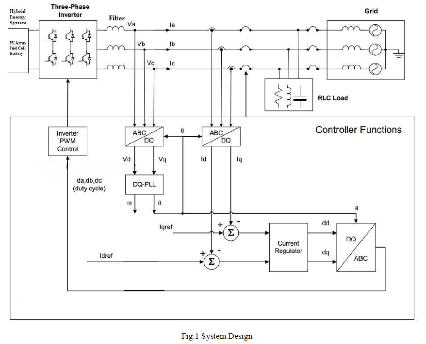 |
III. HYBRID ENERGY SYSTEM
|
| The term Hybrid refers that the combination of two or more systems. In Renewable Energy Systems (RES), the Hybrid energy system refers to the combination of two or more RES devices. This system overcomes the disadvantages of the stand-alone RE conversion systems. |
| Hybrid Energy systems can address limitations such as, |
| Flexibility |
| Efficiency |
| Reliability |
| Emissions |
| Economics |
| A. Need for Hybrid Energy System |
| The disadvantage of stand-alone renewable system is their power generation is intermittent and depends on weather conditions. In the hybrid system, power will be produced even when there is no source for any one RES device. For example, in a Solar-Fuel Cell hybrid system, power production must be ensured even when there is no source for any one of the generation system. In night time, solar input will be zero hence the Fuel Cell can generate the rated supply from the system. In day time, the power can be produced with the help of both the sources.For many applications, the combination of renewable energy sources compares favourably with the fossil fuel based systems, both in regard to their cost and technical performances. Because these systems employees two or more different sources of energy, they enjoy a very high degree of reliability as compared to single source systems such as a standalone solar PV system or a standalone Fuel-Cell system. Application of hybrid energy systems range from small power supplies for remote households, providing electricity for lighting and other essential electrical appliances, to village electrification for remote communities has been reported.The concept of having hybrid power stations is not new, but has gained popularity in recent years. Hybrid energy stations have proven to be advantageous for decreasing the depletion rate of fossil fuels, as well as supplying energy to remote rural areas, without harming the environment. |
| B. Photo Voltaic Cell |
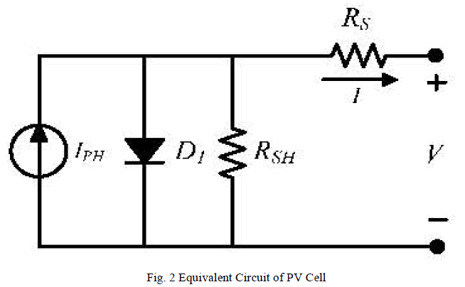
| Fig 2 shows the equivalent circuit of a PV cell. The general model is composed of photo current source, diode, and parallel resistor expressing the leakage current, and series resistor describing the internal resistance to the current flow. |
 |
| The I-V characteristic equation of a PV cell is given as: |
 |
| where Iis a light-generated current or photocurrent, IS is the cell saturation of dark current, q (= 1.6 × 10⁻¹⁹ C) is the electron charge, k (= 1.38 × 10⁻²³ J/K) is Boltzmann constant, T is the cell working temperature, A is the ideal factor, RSH is the shunt resistance, and RS is the series resistance. |
| The photocurrent mainly depends on the solar insolation and cell working temperature, which is given as: |
 |
| where ISC is the cell short-circuit current at a 25 °C and 1 kW/m2, KI is the cell short-circuit current temperature coefficient, Tr is the cell reference temperature, and λ is the solar insolation in kW/m2. On the other hand, the cell saturation current varies with the cell temperature, which is described as: |
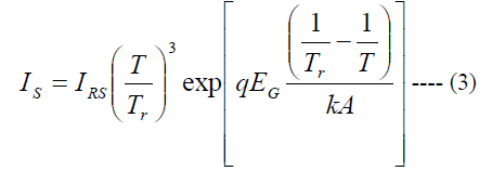 |
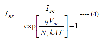
| where IRS is the cell reverse saturation current at a reference temperature and a solar radiation, EG is the bandgap energy of the semiconductor used in the cell. The ideal factor A is dependent on PV technology. |
| The reverse saturation current at reference temperature can be approximately obtained as: |
 |
| Since a PV cell produces very low power, the cells should be arranged in series-parallel configuration on a module to produce enough power. As mentioned earlier, PV array is a group of PV modules which are connected in series and parallel circuit configurations to generate the required current and voltage. |
| For an ideal PV cell (no series loss and no leakage to ground, i.e., RS = 0 and RSH = ∞, respectively). The equivalent circuit of PV cell can be further simplified and Eq. (3.1) can be rewritten as: |
 |
| The photovoltaic panel is modelled in Simulink using the above equations. Sun power SPR-305 PV module is taken as the reference module for simulation and the data sheet details are given in Table-3.1. For the standard test conditions of solar insolation 1 kW/m2 and temperature 25o C, the I-V and P-V characteristics were plotted to verify the correctness of the model. Figure 3.4 and 3.5 show the I-V and P-V characteristics respectively. |
| C. Fuel Cell |
| Fuel cells generate power through the electrochemical reaction between hydrogen and oxygen. The conversion is highly efficient and leaves only water and heat as by-products, which is the main motivation for the increasing interest in the technology. The first fuel cell unit was discovered and developed by Sir William Grove in 1842 with the use of four primitive cells utilizing hydrogen and oxygen. However, it was not practically used until the 1960’s when NASA demonstrated a potential fuel cell application. After such demonstrations, commercial companies became interested in this technology because of its power quality, high efficiency, modularity, and environmental benefits. A fuel cell is an electrochemical energy conversion system, where chemical energy is converted directly into electrical energy and heat. Resulting advantages of this technology are high efficiency almost at partial load, low emissions, and noiselessness (due to nonexistence of moving parts), and free adjustable ratio of electric and heat generation. The basic structure of fuel cells consists of a pair of electrodes and an electrolyte. The fuel which is usually hydrogen, is supplied to the anode where the fuel then is oxidized, yielding electrons, which move through the external circuit. At the cathode, the oxidant is reduced, consuming electrons from the external circuit. Ions move through the electrolyte to balance the flow of electrons through the external circuit. The anode-cathode reactions and the composition and direction of flow of the mobile ion vary with the type of fuel cell. Figure 3.6, explains the operation principle, cathode reactions, and the mobile ion associated with most common fuel cell types. The different types of fuel cell are Alkaline Fuel Cell (AFC), Proton Exchange Membrane Fuel Cell (PEMFC), Phosphoric Acid Fuel Cell (PAFC), Molten Carbonate Fuel Cell (MCFC) and Solid Oxide Fuel Cell (SOFC). |
| D. Battery |
| A rechargeable battery, storage battery, or accumulator is a type of electrical battery. It comprises one or more electrochemical cells, and is a type of energy accumulator. It is known as a secondary cell because its electrochemical reactions are electrically reversible. Rechargeable batteries come in many different shapes and sizes, ranging from button cells to megawatt systems connected to stabilize an electrical distribution network.Several different combinations of chemicals are commonly used, including: lead–acid, nickel cadmium (NiCd), nickel metal hydride (NiMH), lithium ion (Li-ion), and lithium ion polymer (Li-ion polymer).Rechargeable batteries are used for automobile starters, portable consumer devices, light vehicles (such as motorized wheelchairs, golf carts, electric bicycles, and electric forklifts), tools, and uninterruptible power supplies. Emerging applications in hybrid electric vehicles and electric vehicles are driving the technology to reduce cost and weight and increase lifetime.Grid energy storage applications use rechargeable batteries for load levelling, where they store electric energy for use during peak load periods, and for renewable energy uses, such as storing power generated from photovoltaic arrays during the day to be used at night. By charging batteries during periods of low demand and returning energy to the grid during periods of high electrical demand, load-levelling helps eliminate the need for expensive peaking power plants and helps amortize the cost of generators over more hours of operation.In this project a nickel–metal hydride battery is used. NiMH or Ni– MH, is a type of rechargeable battery. Its chemical reactions are somewhat similar to the largely obsolete nickel– cadmium cell (NiCd). NiMH use positive electrodes of nickel oxyhydroxide (NiOOH), like the NiCd, but the negative electrodes use a hydrogen-absorbing alloy instead of cadmium, being in essence a practical application of nickel– hydrogen battery chemistry. A NiMH battery can have two to three times the capacity of an equivalent size NiCd, and their energy density approaches that of a lithium-ion cell. |
IV. SYNCHRONOUS REFERENCE FRAME
|
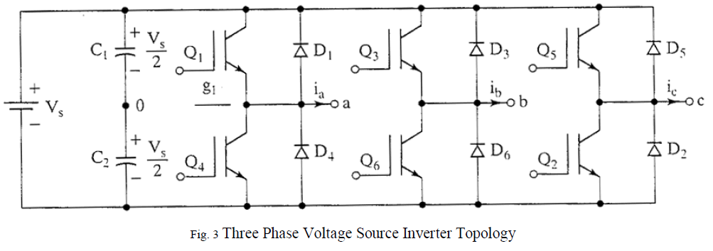
| Since the generated voltage from renewable energy sources is DC, we need inverter for converting DC voltage to AC before connecting it to grid. Grid is a voltage source of infinite capability. The output voltage and frequency of inverter should be same as that of grid frequency and voltage. The output of grid connected inverter can be controlled as a voltage or current source and pulse width modulated (PWM) voltage source inverters (VSI) are most widely used. The three phase full bridge inverter topology is the most widely used configuration in three phase systems. The inverter selected is current controlled voltage source inverter. IGBT’s are used as the switching element which is operated at a frequency of 20 KHz. Bi-polar PWM technique is used in which switches in each pair are turned ON and OFF simultaneously and output voltage varies between –Vs and +Vs, where Vs is the input voltage of inverter which is considered as battery as shown in figure 3. As in single-phase VSIs, the switches of any leg of the inverter (Q1 and Q4, Q3 and Q6, or Q5 and Q2) cannot be switched on simultaneously because this would result in a short circuit across the dc link voltage supply. The output of each leg depends only on input voltage and switch status and is independent of load current. |
 |
| Transformations from a three-phase system to different two-phase systems can be used in order to avoid controlling coupled ac currents and voltages. These are based on the fact that in a balanced three-phase system there are only two independent current/voltages, thus the third current/voltage can be expressed by the other two. These systems are often referred to as reference frames, where the frame is the axis system of the transformed system. |
| A. Inverter Control using Synchronous Reference Frame Technique |
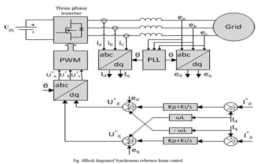 |
| A block diagram of the Synchronous reference frame ordqcontrol is represented in figure 4. Since the controlled current has to be in phase with the grid voltage, the phase angle used by the abc→ dqtransformation module has to be extracted from the grid voltages. Phase-locked loop (PLL) technique is adopted to provide the phase information of the grid voltage, which is needed to transform the grid currents Id and Iq in the in the dq frame and then transform the voltage control signal back to the abc frame. Two PI controllers are adopted to regulate Id and Iq according to the current reference Id* and Iq*, which determines the real power and reactive power exchanged with the grid respectively. The inverter is assumed to be powered by a constant DC power source and hence no controller is needed to regulate the DC link voltage. Otherwise a controller can be introduced. The reference for the reactive current is usually set to zero, if the reactive power control is not allowed. In the case that the reactive power has to be controlled, a reactive power reference must be imposed to the system. Thedqcontrol structure is normally associated with proportional–integral (PI) controllers since they have a satisfactorybehaviour when regulating dc variables. For improving the performance of PI controller in such astructure as depicted, cross-coupling terms and voltage feed forward are usually used. These are neglected in this project work. |
| This scheme has the particular advantage of independent control of the real and reactive power components of the grid currents, which can be directly translated into real and reactive power. As a result, it is possible to set the real and reactive power sent to the grid directly. |
| B. Grid Synchronization |
| The inverter output current that is injected into the utility network must be synchronized with the grid voltage. The objective the synchronization algorithm is to extract the phase angle of the grid voltage. The feedback variables can be converted into a suitable reference frame using the extracted grid angle. Hence, the detection of the grid angle plays an |
| essential role in the control of the grid-connected inverter. The synchronization algorithms should respond quickly to changes in the utility grid. Moreover, they should have the ability to reject noise and the higher order harmonics. Many synchronization algorithms have been proposed to extract the phase angle of the grid voltage such as zero crossing detection, and phase-locked loop (PLL). |
V. SIMULATION AND RESULTS
|
| The simulations were carried out using MATLAB/ Simulink R2010a package. The blocks used are taken from SimPowerSystems toolbox. This chapter details the simulation of the hybrid energy system (PV array, fuel cell and battery) and grid connected inverter. |
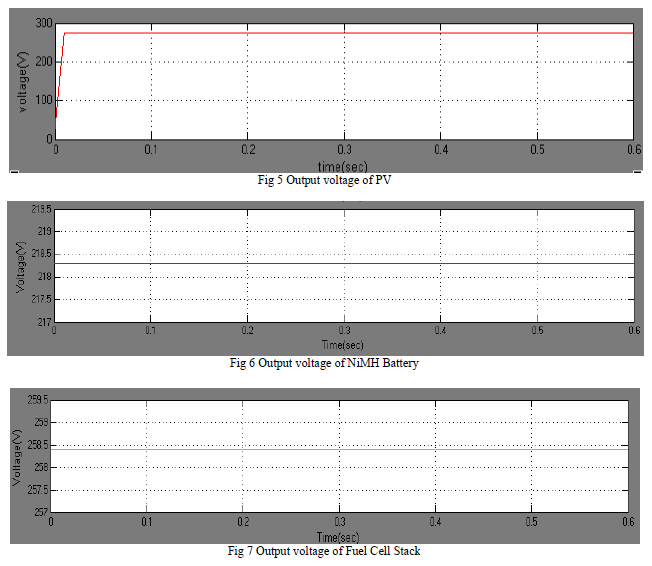
| PV Array is used to get a dc output voltage of 271V as shown in Fig 5. The fuel cell and battery were implemented using the generic fuel cell and generic battery block available in SimPowerSystems Toolbox/ExtraSources.The Nickel- Metal Hydride battery type and Alkaline fuel cell (AFC) 2.4 KW, 48V dc are used in this simulation. Four AFC are connected in series to supply 258.4V dc. The battery is rated at 185V dc and its fully charged voltage is 218V. The Output Voltage of the Battery and Fuel Cell is shown in Fig 6 and Fig 7 respectively |
 |
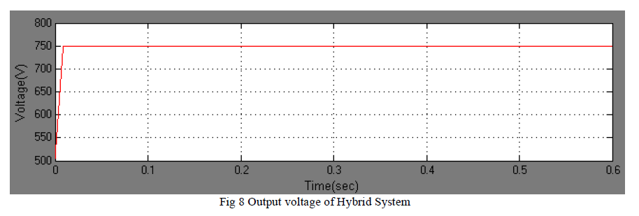
| Thus the three sources added up supply a total dc voltage of 750V, which serves as input voltage for the inverter. The output waveform of the hybrid system is shown in Fig8. |
 |
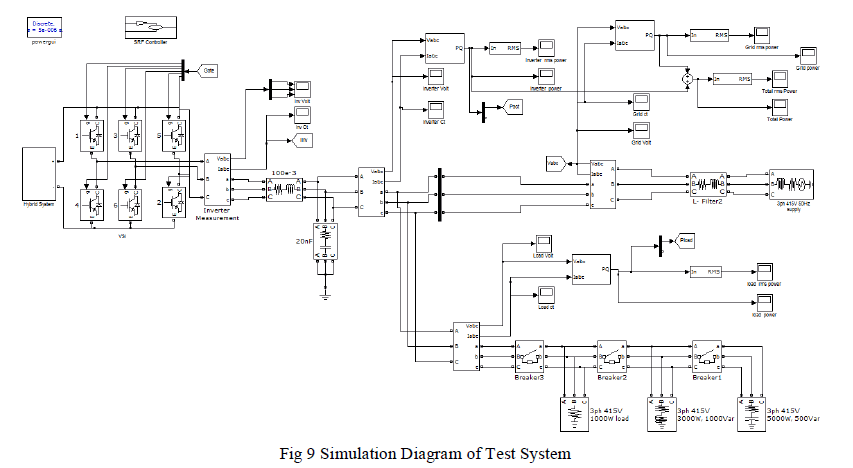
| The test system is shown in Fig 9. |
 |
| The output voltage of the inverter is shown in Fig. 10. The voltage at the output of inverter is 415*√2 which is 586.89Volt(peak to peak). |
 |
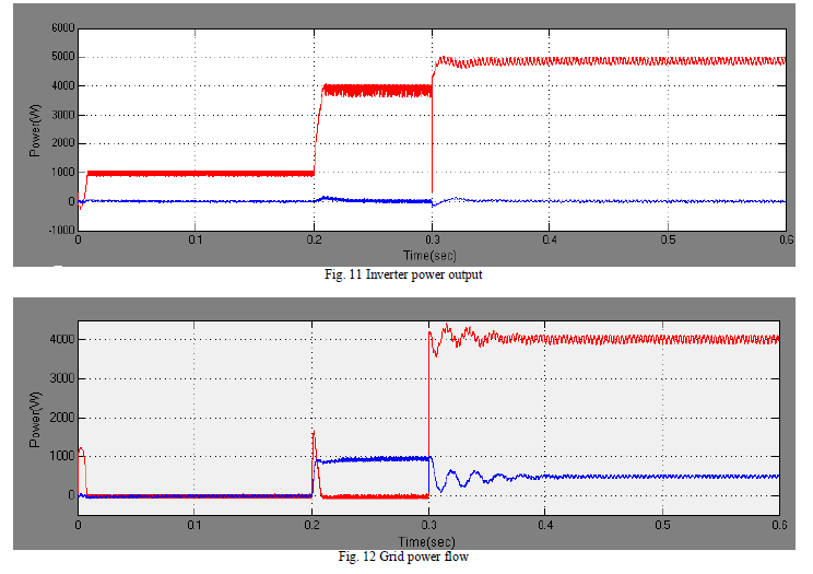
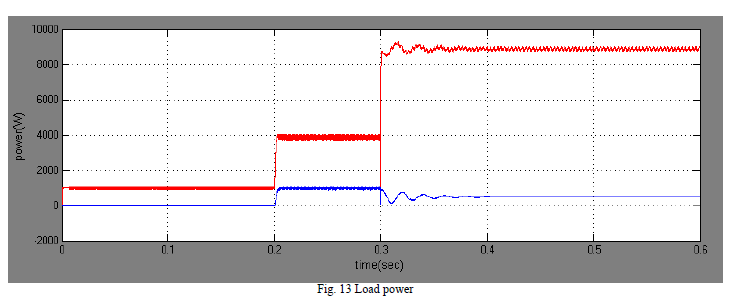
| To simulate the response of the power flow control system during changes in the active and reactive power references, we operated the inverter with a sequence of power changes by switching on the loads using a circuit breaker. At the beginning of the simulation, the inverter was started with P_ref = 1000 W and Q_ref = 0 Var. At time 0.2s, Q_ref was changed to 1000Var while P_ref was increased to 4000W. Finally, at time 0.3s, P_refwas imposed from 4000W to 9000W while Q was maintained at 500Var. The simulated power flow waveforms are shown in Fig.11, Fig. 12, Fig.13 respectively. We can see from figures 5.13-5.15 that the inverter output powers are following the reference set point values.When the demand increased beyond the 5KW rated capacity of the inverter, the power is supplied by the grid through the point of common coupling (PCC).It is evident that the biggest transient occurs during the step change of reactive power from leading VAR to lagging VAR. The transients are mitigated very fast and are damped in less than three cycles. The results show that the inverter output power follows the reference power commands with considerable accuracy. |
 |
 |
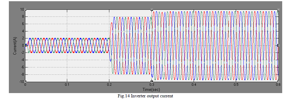
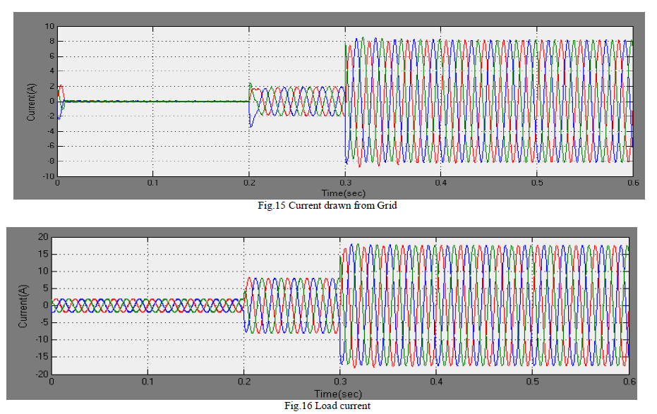
| In the simulation, the inverter is operating in current control mode. The initial load on the system is 1000W. The 2A peak-to-peak current (rms value of 1.4A) required by the load is supplied by the inverter. When the real power reference increases to 4000W at 0.2s, the inverter starts supplying 8A (5.5A rms). After 0.3s the load has increased to 9000W and the inverter is operating at its maximum rating of 5000W and remaining power is drawn from the grid. Since only real power is being supplied by the inverter the reactive power demand is satisfied by the grid. The simulation results for current control mode are shown in Fig.14, Fig. 15, Fig.16 respectively.All waveforms are in phase values. The simulation suggests that the inverter current control loop does a very good job of maintaining the reference current when operated in the utility connected mode. |
 |
 |
VI. CONCLUSION
|
| This paper presents complete design and implementation of three phase grid connected inverter for renewable energy. The different types of renewable sources were studied and a hybrid energy system comprising of PV array, Fuel Cell and battery was stimulated in MATLAB/Simulink. The objectives for this work have been successfully realized through analysis and simulation in MATLAB/Simulink. The effectiveness of the synchronous reference frame technique has been proved through numerous simulation results. The THD of the injected current was kept below the specified international standards. |
References
|
- B. K. Prusty, Dr S M Ali, D. K. Sahoo, “Modeling and Control of Grid-Connected Hybrid Photovoltaic/Battery Distributed GenerationSystem”, International Journal of Engineering Research & Technology (IJERT).
- M.Abdulkadir, A. S. Samosir and A. H. M. Yatim, “Modeling and simulation based approach of photovoltaic system in simulinkmodel”,ARPN Journal of Engineering and Applied Sciences.
- G. Adamidis and G. Tsengenes, “Three phase grid connected photovoltaic system with active and reactive power control using instantaneousreactive power theory”, II International Conference on Renewable Energies and Power Quality, pp. 8 – 16, March 2010.
- Ahmed Abdalrahman, AbdalhalimZekry, Ahmed Alshazly, “Simulation and Implementation of Grid-connected Inverters”, InternationalJournal of Computer Applications (0975 – 8887).
- S.K. Chung, “Phase lock loop for grid connected 3 phase power conversion system”, IEE Proc. Electr. Power Application, Vol. 147, pp. 213 -219, May 2000.
- Francisco D Freijedo, Jesus Dovel& Oscar Lopez, “Grid synchronization methods for power converters”, Industrial Electronics pp. 522- 529,2009.
- FredeBlaabjerg , Remus Teodorescu and Marco Liserre, “Overview of control & grid synchronization for distributed power generationsystems”, IEEE transaction on Industrial Electronics, Vol. 53, pp. 500 – 513, Oct- 2006.
- Mateus F Schonardie and DenizarC Martins, “Application of the dq0 transformation in the three phase grids connected PV system with activeand reactive power control”, II Power Electronics Specialists Conference. pp. 1202 – 1208, June 2008.
- Yuan Liao, Wen Fan, Aaron Cramer, Paul Dolloff, ZongmingFei, Meikang Qui, Siddhartha Bhattacharyya, Larry Holloway, Bob Gregory,“Voltage and Var Control to Enable High Penetration of Distributed Photovoltaic Systems”, North American Power Symposium (NAPS),2012.
|