International Journal of Advanced Research in Electrical, Electronics and Instrumentation Engineering
ISSN ONLINE(2278-8875) PRINT (2320-3765)
ISSN ONLINE(2278-8875) PRINT (2320-3765)
G.S.C.N.Durga Rao 1, Ch.V.N.Raja 2, D.Narendra Kumar 3
|
| Related article at Pubmed, Scholar Google |
Visit for more related articles at International Journal of Advanced Research in Electrical, Electronics and Instrumentation Engineering
SCARA Robots are mainly suitable for pick-and-place operations such as part handling, assembly, etc. Till now, many controllers are designed (like Trial and error, ZN PID and IMC etc) to control a Scara robot to meet desired position. The main drawbacks of those controllers are if plant parameter changes automatically system performance changes. In this paper, to overcome this drawback Quantitative Feedback Theory (QFT) has proposed for single and two link SCARA Robot.
Keywords |
||||||||||||||||||||||||||||
| SCARA, QFT, Robust Controller, IMC, PID | ||||||||||||||||||||||||||||
INTRODUCTION |
||||||||||||||||||||||||||||
| SCARA (Selective Compliance assembly Robot Arm) robots are horizontally articulated manipulator with a vertical joint at the wrist end. Generally the robot configuration has one vertical (linear) and two revolute joints, it was designed by Professor Makino of Yamanashi University, Japan, and they are ideally suited for operations in which the vertical motion requirements are small compared to the horizontal motion requirements. Such an application would be assembly work where parts are picked up from a parts holder and moved along a nearly horizontal path to the unit being assembled. Fig.1 shows the Two link scara robot model. Potential problems arise mainly due to the positioning errors in assembly. The Adaptive and model-based control strategies cannot overcome the structure of uncertainties of a robotic system . Dynamic models of robot manipulators consist of highly non-linear coupled second-order differential equations. Non-linearity and parameter variations in real systems prevents, ordinary linear time-invariant control schemes achieving a satisfactory control performance. Linearization techniques for the robust control of robot manipulators with uncertainty have been the subject of many research studies. For example as referenced in [1], Kawabata et al. (1993) and Takayanagi et al. (1993) studied robust position controllers for a two-link manipulator. Tern et al. [2] presented a dynamic modelling and linearization technique for a SCARA robot. CH.V.N Raja presented Control of two link Scara robot using IMC PID controller[3]. | ||||||||||||||||||||||||||||
| The SCARA robot is used for clean-room applications, such as wafer and disk handling in the electronics industry. It performs many tasks in a fraction of the time it would take a human. Whether constructing something intricate, such as a computer motherboard, or large and hulking, such as the frame of an 18-wheel semi truck, this tool helps increase production and lower costs because of its efficiency. | ||||||||||||||||||||||||||||
| Many practical systems that have high uncertainty levels in their open-loop transfer functions which makes it very difficult to create suitable stability margins and good performance in command following problems for a closed-loop system. Therefore, a single fixed controller in such systems is found among the ‘robust control’ family. Quantitative feedback theory (QFT) is a robust feedback control-system design technique which allows the direct design to closed-loop robust performance and stability specifications [4]. | ||||||||||||||||||||||||||||
| QFT not only uses transfer function approach but also takes phase information into account in the design process. The unique feature of QFT is that the performance specifications are expressed as bounds on the frequency-domain response. Meeting these bounds implies a corresponding approximate closed-loop realization of the time-domain response bounds for a given class of inputs and for all uncertainty levels in a given compact set. | ||||||||||||||||||||||||||||
| For parametric uncertain systems plant templates must be generated prior to the QFT design (at a fixed frequency, the plant’s frequency response set is called a template). Given the plant templates, QFT converts the closed-loop magnitude specifications into magnitude constraints on a nominal open-loop function (these are called QFT bounds). A nominal open-loop function is then designed to simultaneously satisfy its constraints as well as to achieve nominal closed-loop stability. In a two-degree-of-freedom design, a pre-filter is designed after the loop is closed (i.e. after the controller has been designed) [5]. | ||||||||||||||||||||||||||||
SCARA ROBOT |
||||||||||||||||||||||||||||
| Introduction: SCARA robot is widely used for pick and place operations, factory automation as Assembly products robot, soldering robot etc. | ||||||||||||||||||||||||||||
| Consider the feedback system shown in Fig.2.This system has a two-degree-of-freedom structure. In this diagram P(s) is uncertain plant belongs to a set P(s) ∈ {P(s, α); α∈ P} where α is the vector of uncertain parameters, which takes the values in ÃÂÃâ¢. G(s) is the fixed structure feedback controller and F(s) is the prefilter, and D(s) is the disturbance at the plant output. | ||||||||||||||||||||||||||||
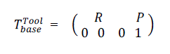
| The link matrix shows the position and direction of the robot, with respect to a base coordinate system. | ||||||||||||||||||||||||||||
 |
||||||||||||||||||||||||||||
| Where P is a vector of position and R is a vector of direction for the robot. The shaping space of the robot has six dimensions because every robot position can be found in terms of the coordinates (Px, Py, Pz) and the direction characteristics of yaw, pitch, and roll. The reversed kinematics problem can be considered as: for each P and R for the robot, find the space variation value to satisfy equation (1) | ||||||||||||||||||||||||||||
| Dynamics of the SCARA robot: When the Newton–Euler equations are evaluated symbolically for any manipulator, they yield a dynamic equation which can be written in the form | ||||||||||||||||||||||||||||
| Where D(q) is the nxn mass matrix of the manipulator C(q,qÃâ¹Ãâ¢) is an nx1 vector of centrifugal and coriolis terms, and G(q) is an nx1 vector of gravity terms. | ||||||||||||||||||||||||||||
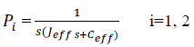
| System Linearization: In the QFT method, the non-linear plant is converted into a family of linear and uncertain processes. Two techniques have been reported in the literature for this conversion: the linear time-invariant equivalence (LTIE) of non-linear plants, and the non-linear equivalence disturbance attenuation technique [6]. In this paper the LTIE method is used.Taghirad and Afshar [7] and Gharib et al. [8] have proposed a linearization technique, which can predict the behavior of a real non-linear system in a working space. Each link is considered as a load system which is connected to the motor. Then, ignoring all non-linear terms in equation (2) it becomes possible to write a simple governing equation for each link | ||||||||||||||||||||||||||||
| Where is the angular velocit is the acceleration and is the required torque. The linearized transfer function for each link is | ||||||||||||||||||||||||||||
 |
||||||||||||||||||||||||||||
| Link 1 Ceff = [0.75 5.2], Jeff = [0.2 0.5] Link 2 Ceff = [0.22 2.12], Jeff = [0.14 0.26] | ||||||||||||||||||||||||||||
QFT CONTROLLER DESIGN |
||||||||||||||||||||||||||||
| This section uses the QFT method [9, 10] to design a controller for a SCARA robot. The non-linear plant needs to be converted to family of linear and uncertain processes and the techniques introduced in section 2 need to be implemented. The objectives of this section are to synthesize suitable controllers and prefilters such that: | ||||||||||||||||||||||||||||
| (a) The closed-loop system is stable; | ||||||||||||||||||||||||||||
| (b) It can track desired inputs; | ||||||||||||||||||||||||||||
| (c) cross-coupling effects can be studied by using suitable robust disturbance rejection bounds. | ||||||||||||||||||||||||||||
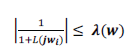
| The stability margin can be defined by | ||||||||||||||||||||||||||||
| The tracking specification is an overshoot of 20 per cent and a settling time of 0.2 sec for all plant uncertainties which can be described with the second-order system | ||||||||||||||||||||||||||||
| Where α(j) and (j) are lower bound and upper bound respectively. T(j) is the input–output relation from the input R(s) to the output Y(s). Suitable robust disturbance rejection bounds to reduce the cross-coupling effects between joints are | ||||||||||||||||||||||||||||
 |
||||||||||||||||||||||||||||
| As a first step the plant uncertainty (template) must be defined and the computed boundary of plant templates for link 1 is shown in Fig. 3. The robust margin bounds are depicted in Fig.4 and the robust disturbance rejection and reference tracking bounds are shown in Figs 5 and 6 respectively. The intersection bounds or the robust performance bound is shown in Fig.7.The loop shaping and pre-filter results are presented in Figs.8 and 9. Fig.11 shows Step response for all parametric uncertainty systems. | ||||||||||||||||||||||||||||
SIMULATION RESULTS |
||||||||||||||||||||||||||||
| For link1: | ||||||||||||||||||||||||||||
| Fig 3 shows that plant template boundaries for link 1 with open loop phase in X axis and open loop magnitude in Y axis. | ||||||||||||||||||||||||||||
| Fig 4 shows stability margin specification boundaries for link 1 with open loop phase in X axis and open loop magnitude in Y axis | ||||||||||||||||||||||||||||
| Fig 5 shows output disturbance rejection specification boundaries for link 1 with open loop phase in X axis and open loop magnitude in Y axis. | ||||||||||||||||||||||||||||
| Fig 6 shows reference tracking boundaries for link 1 with open loop phase in X axis and open loop magnitude in Y axis. | ||||||||||||||||||||||||||||
| Fig 7 shows intersection boundaries for link 1 with open loop phase in X axis and open loop magnitude in Y axis. | ||||||||||||||||||||||||||||
| Fig 8 shows the controller design graph between open loop phase in X axis and open loop gain (dB) in y axis. | ||||||||||||||||||||||||||||
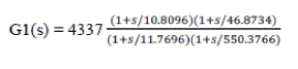
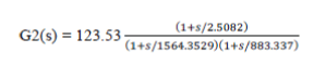
| The controller for link 1 is | ||||||||||||||||||||||||||||
 |
||||||||||||||||||||||||||||
| Fig 9 shows the prefilter design graph between frequency in X axis and magnitude in Y axis. | ||||||||||||||||||||||||||||
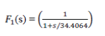
| The related pre-filter for the robot link1 is | ||||||||||||||||||||||||||||
 |
||||||||||||||||||||||||||||
| Fig 10 shows stability specification analysis between frequency in X axis and magnitude in Y axis. | ||||||||||||||||||||||||||||
| Fig 11 shows Step response for all parametric uncertainty systems with frequency in X axis and magnitude in Y axis. | ||||||||||||||||||||||||||||
| In order to save the space only the controller design process is shown for first link. The related controller and prefilter transfer function for link 2 are found and Fig.12 shows the Step response for link 2, by considering all the system parametric uncertainty. | ||||||||||||||||||||||||||||
 |
||||||||||||||||||||||||||||
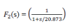
| The pre-filter for the link2 is | ||||||||||||||||||||||||||||
|
|
||||||||||||||||||||||||||||
 |
||||||||||||||||||||||||||||
| In fig 12, X axis indicates frequency in X axis and magnitude in Y axis for the step response for all parametric uncertainty systems. | ||||||||||||||||||||||||||||
COMPARISONS |
||||||||||||||||||||||||||||
| Comparison of step response for four controllers | ||||||||||||||||||||||||||||
| Fig 13 shows step response comparisons for IMC, QFT, Trial and error, ZN PID Controllers for link 1 | ||||||||||||||||||||||||||||
| Fig 14 shows step response comparisons for IMC, QFT, Trial and error, ZN PID Controllers for link 2 | ||||||||||||||||||||||||||||
CONCLUSION |
||||||||||||||||||||||||||||
| In this paper we have proposed QFT Controller for single and Two link SCARA Robot to achieve desired position i.e.; required time domain specifications. From the simulation results, we have concluded that QFT gives the required response for parametric uncertainty system as compared to Conventional Control methods those are trial and error, ZN PID, and IMC Controllers. | ||||||||||||||||||||||||||||
Figures at a glance |
||||||||||||||||||||||||||||
|
||||||||||||||||||||||||||||
References |
||||||||||||||||||||||||||||
|


