Keywords
|
| CORDIC, FFT, Rotation CORDIC, Vectoring CORDIC . |
INTRODUCTION
|
| A modern signal processing application requires a high computational power for technical demands that can be fulfilled only by ASIC. Though ASIC can meet all the technical demands it has the disadvantage such as it is inflexible, costly and economical only for mass products. So the system designers are striving to replace the hardware based solution with a software based solution. |
| Due to these reasons that most commonly used programmable device i.e, DSP often lack the required power needed for the design. In order to provide the solution between these two extrema such as programmable signal processing and dedicated hardware a reconfigurable computing is developed.Within the framework of MORTEX project, this paper provides a solution by replacing the MAC based FFT[1][2] by a purely CORDIC based FFT. |
| The Coordinate Rotation Digital Computer (CORDIC) was introduced by Volder [3] that provides an effective method for computing iteratively the rotation of the two dimensional vector using only shift and add operation. The CORDIC algorithm is used in many applications such as digital filtering, modulation, Fast Fourier Transform (FFT), and Signal Value Decomposition(SVD). The CORDIC based architecture are a very appealing alternative to multiply and add hardware. |
| In [4] it was shown that the Rake receiver was replaced by CORDIC based algorithm that uses the reconfigurable hardware accelerator[5] [6], which even results in a better performance. An 8 point FFT used in WLAN is implemented on the same architecture of Rake receiver is explained in this paper.Therefore we have derived a reconfigurable architecture for a mobile multi standard terminal and the main processing blocks of the WLAN and UMTS baseband can be replaced by this programmable architecture. |
| This paper is organized as follow: Section I gives the Introduction of the CORDIC algorithm and FFT of Digital Signal Processing. Section II describes about the MAC based algorithm. Section III explains about the CORDIC based algorithm, the solution approach and the proposed implementation. Section IV show some simulation results in a WLAN environment, the performance of proposed technique and the last section V concludes the paper and followed by the references. |
MAC BASED FFT
|
| The number of complex multiplication and addition operations required by the simple forms both the Discrete Fourier Transform (DFT) and Inverse Discrete Fourier Transform (IDFT) is of order N2 as there are N data points to calculate, each of which requires N complex arithmetic operations. |
| For an input vector X and length n, the DFT is a vector X length n, with n elements: |
 |
| In computer science jargon, we may say they have algorithmic complexity O(N2) and hence is not a very effective method. If the proposed method is not better than this then the DFT will not be very useful for the majority of practical DSP applications. But ,there are large number of different 'Fast Fourier Transform' (FFT) algorithms that enable the calculation the Fourier transform of a signal much faster than a DFT. |
| As the name suggests, FFTs are algorithms for quick calculation of discrete Fourier transform of a input vector. The FFT that includes DFT algorithm reduces the number of computations needed for N points from O(N 2) to O(N log N) where log is the base-2 logarithm. The function that is to be transformed is not harmonically related to the sampling frequency, but it looks like a ‘sinc’ function (sin x). |
| The 'Radix 2' algorithms are useful if N is a regular power of 2 (N=2p). Let us assume that algorithmic complexity provides a direct measure of execution time and that the relevant logarithm base is 2 then as shown in Fig 1, ratio of execution times for the (DFT) versus (Radix 2 FFT) (denoted as ‘Speed Improvement Factor’) increases tremendously with increase in N. |
| The FFT are the most advanced one because there are several numbers of FFT algorithms used. There are two Radix 2 algorithms, called as 'Decimation in Frequency' (DIF) and 'Decimation in Time' (DIT) algorithms. Both the algorithms depend on the recursive decomposition of an N point transform into 2 (N/2) point transforms. The decomposed process can be applied to any composite (non prime) N. The method is simple if N is divisible by 2 and if it is a power of 2, then the decomposition can be done recursively until the trivial '1 point' transform is reached. |
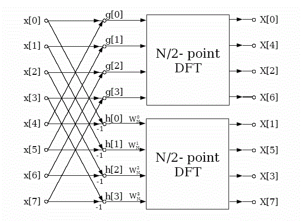
| The Fig. 1 shows the first stage of the 8-point DIF algorithm.The radix-2 decimation-in-frequency FFT is an important algorithm obtained by the divide and- conquers approach. |
| The entire process involves v = log2 N stages of decimation, where each stage involves N/2 butterflies of the type shown in the Fig. 2. The decimation, however, causes shuffling in data. |
| Here WN = e –j 2Π/ N, is the Twiddle factor. |
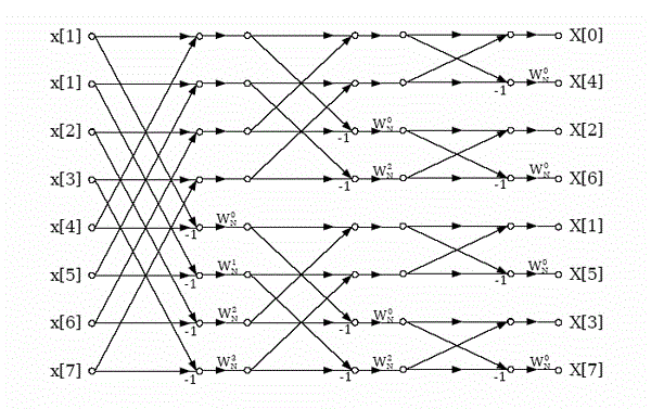
| Consequently, the computation of N-point DFT via this algorithm requires (N/2) log2 N complex multiplications. For design purposes, the eight-point decimation-in frequency algorithm is shown in the Fig.3. We observe, that the output sequence has been occurred in a bit reversed order for the applied input. Furthermore, if suppose that the computation is abandoned in a particular place then both the input and output can be achieved in the normal order. |
CORDIC BASED FFT
|
| Verilog HDL code implements an 8 point decimation-in-frequency algorithm using the butterfly structure. The number of stages v in the structure shall be v = log2 N. In our case, N = 8 and hence, the number of stages is equal to 3. There are numerous number of ways to implement these 3 stages. Some of them are, |
A Iterative Architecture
|
| In iterative architecture only one stage is repetitively used for three times in decimation that provides a hardware efficient circuit for all the 12 set adders and subtractors in one set. Out of these 3 stages, the first stage will requires only 2 CORDICs and each will take 8 clock pulses for each computation. The remaining two stages does not require any CORDIC even though they have to be rotated the data by 0o or -90o using the CORDIC, that will take 16 clock pulses. The rotation of data for the whole process can be achieved by using the 2’s complement and the Bus exchange that would require only less hardware. |
| In this when one of the data is being computed, the process has to wait until it has been completed for 36 clock pulses. |
| Thus, Time Taken for computation = 24 clock cycles No. of 12 bit adders and sub tractors = 16 |
B Pipeline Architecture
|
| In pipeline architecture instead of using one stage, three stages are used separately for everydecimation and the other case is that 12 bit adders require 3 sets of sixteen adders. By using this architecture the complexity and the delay has been reduced drastically at each stage separated from other register bank. When the previous data is set then another set of data is sent serially into the register input. At the last the 3 stages works simultaneously as a total net effect. |
| Though the pipeline architecture has many advantages compared to iterative one it does not consider as the valid option because of large amount of hardware used. Besides, this provides an improvement in architecture merely as 1 clock cycle. Thus, Time Taken for computation = 8 clock cycles No. of 12 bit adders and subtractions = 40 |
C Proposed Method
|
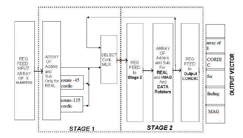
| To balance between the pipeline and iterative architecture the proposed method will use the two stages for calculating the three decimations. The first stage will be implemented as in the normal fashion but the remaining two stages are combined together to form one stage since it does not require any CORDIC. MUX is used to control the data that has been given as the input which in turn controlled by COUNTER MUX. In the first stage the adders and subtractors require only the real data while the next stage requires both real and imaginary data. |
| Thus, Time Taken for computation = 10 clock cycles No. of 12 bit adders and subtractors = 24 |
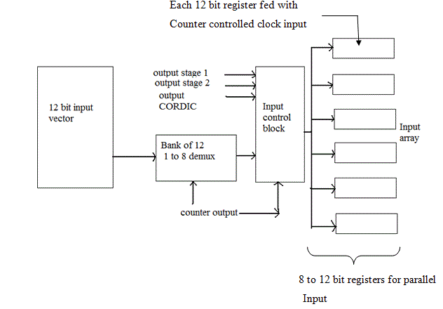
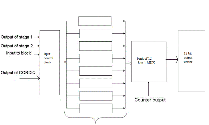
| The input data is sent serially and depends of the counter output the data will pass into the 12 bit register for parallel input. In this only 8 clock pulses are used in this process as shown in the Fig.4. Then later the data acts as an input for asynchronous adders and subtractors. |
| The asynchronous output is given as an input to the CORDIC block. Out of many outputs the output from 0 to 5 and 8 are available for the next stage but only after the 8 clock pulse is achieved i.e., the output is ready for the second stage only after 16 clock pulses. After the desired clock pulse is achieved the output is passed to next stage.The stage 2 in this circuit jointly implements both the second and third decimations in the architecture simply because there is no CORDIC required in these stages and rotation required is -90o or 0o.Thus, a+bj on rotation by -90o becomes b-aj, i.e. simply 2’s complement of ‘a‘. |
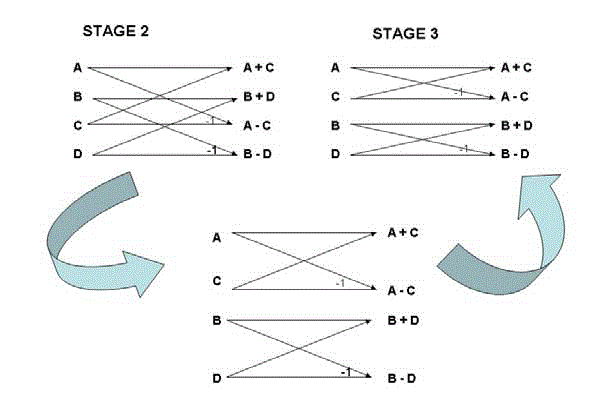
| The Fig.5 displays the block diagram of the butterfly scheme in which the input data is varied to combine both the stage into single stage. If suppose the inputs of one or two is flipped then we get another stage. The second and the third stages are asynchronous in nature so they require only a single clock pulse for each computation. |
| After we get the output at the end of the 3rd stage, it is loaded into the VECTORING CORDIC. This results in a complex number of a magnitude as Real + Imag * j that takes 8 clock cycles to compute. |
| The 8 outputs are then sent to the output port serially for next 8 clock cycles. The output architecture Fig.7 shows how the output is channeled into 12 bit port. |
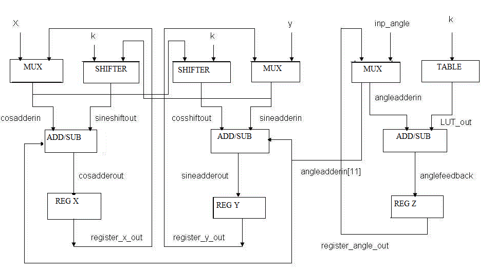
| 1) Rotation CORDIC : To rotate a vector x + jy by inp_angle it uses the standard CORDIC algorithm and it takes 8 iteration to complete. When iteration starts, the x, y and the angle registers are initiated to the original values of x, y and inp_angle respectively. The x and y registers either add or subtract the shifted values of y and x depending on the sign of the angle accumulated in angle register respectively at every iteration. |
| The block diagram is as follows: |
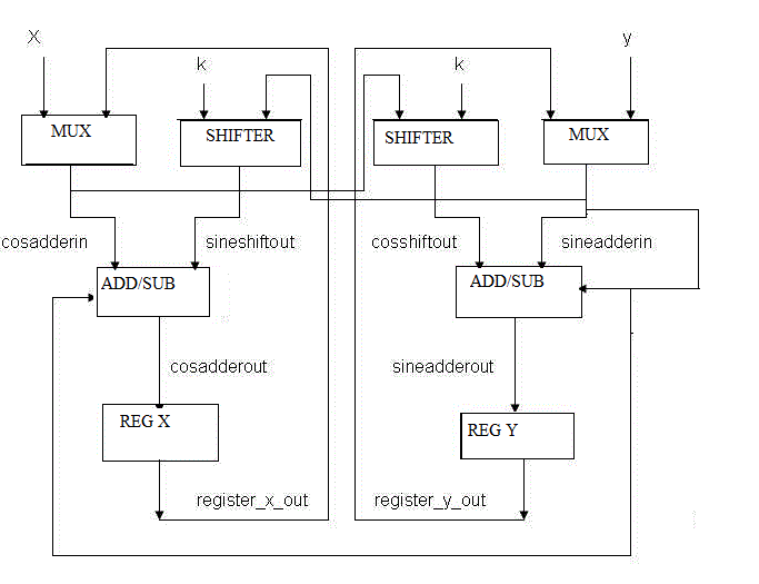
| 2) Vectoring CORDIC: This module makes a vectoring CORDIC that computes the magnitude (mag) of a vector x + j*y. Note that the CORDIC gain factor compensation is not done in this vectoring CORDIC.As such, the magnitude values are actually multiplied by the CORDIC gain Factor of 1.647.The vectoring CORDIC uses the same concept as that explained in the rotation CORDIC. |
| When started, the x and y registers are initiated with the original values of x & y respectively. Then, try to iteratively rotate the vector so that it comes onto the x - axis and the magnitude then is equal to this x component. To achieve this, the x and y registers iteratively add or subtract the shifted values of y and x respectively so that the y register dies down to zero. |
| At the start of the iterations, we need to bring the vector in the region +90 to -90 degrees. The original vector x + j*y, if in the 1st or the 2nd quadrant, is rotated by -90 degrees to get it in the region +90 degrees to -90 degrees. If the vector x + j*y is in the 3rd or the 4th quadrant, it is rotated by +90 degrees to get it in region +90 degrees to -90 degrees. |
SIMULATION RESULTS
|
| The CORDIC FFT architecture uses certain blocks as Twelve Bit Adder, Counters and the CORDIC blocks themselves require Shifters and registers. The output of CORDIC FFT is compared with the MAC based FFT and the results are analysed. |
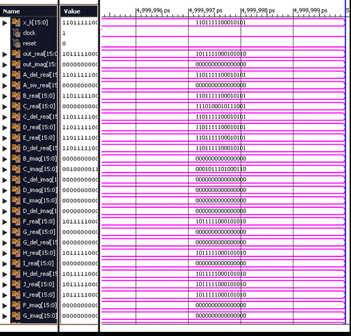
| The FFT consists of the butterfly stage, shifter unit and control unit. The input to the main block is given as x_k which is of 16 bit and the output is represented as out_real and out_imag. |
| The LUT is required by the angle accumulator register in the rotation cordic module to compute the angle values that need to be added or subtracted from the accumulated angle. The angle values stored are stored in the following format: |
| ïÃâ÷ 12 bit representation is used. |
| ïÃâ÷ The MSB, bit11, has a binary weight of -180 degrees. |
| ïÃâ÷ The next bit, bit10 has a binary weight of +90 degrees. |
| ïÃâ÷ Then, the next successive bits, bit(9:0) have binary weights of +90/(2^n) where n varies from1 for bit9 to 10 for bit 0. Thus the least count or the least angle that can be represented in this system is 90/(2^10) = 0.087890625 degrees. |
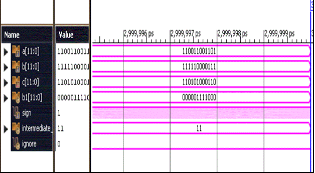
| Fig.12 shows the full adder module is used to make a 'cascaded' 12 bit adder block. As explained for the full adder, this adder works as carry bypass. This 12 bit adder is used as an adder/subtractor for two 12 bit numbers: a & b.The addition subtraction depends on the sign bit. sign = 0 means addition, sign = 1 means subtraction. For subtraction, using an EXOR inverter array, the 1's complement of b is passed to the cascade of 3 full adder blocks along with making the input sign = 1. |
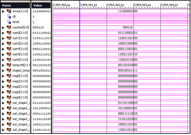
| The main module consists of an input array which is of 12 bits.Counter is used in this in which according to the counter input each stage of the butterfly output will be produced.For example when counter input is 000001 and 000100 then the corresponding output outr0 will be produced. |
CONCLUSION
|
| The key contribution of this project is the realization of FFT using the CORDIC algorithm. The CORDIC algorithm that has been used is simply a shift and add operation which is of an efficient one and improve the performance in the design.The CORDIC based FFT is compared with the MAC based FFT in which real and imaginary part multiplication is omitted instead of that rotation is performed using the CORDIC.Thus the designed CORDIC based FFT provides a better performance than the MAC based FFT. |
ACKNOWLEDGEMENT
|
| The author thanks the Department of Electronics and Communication Engineering, Bannari Amman Institute of Technology for the support rendered for carrying out this project. |
Figures at a glance
|
 |
 |
 |
 |
 |
| Figure 1 |
Figure 2 |
Figure 3 |
Figure 4 |
Figure 5 |
|
 |
 |
 |
 |
 |
| Figure 6 |
Figure 7 |
Figure 8 |
Figure 9 |
Figure 10 |
|
 |
 |
 |
| Figure 11 |
Figure 12 |
Figure 13 |
|
| |
References
|
- A. V. Oppenheim and R. W. Schafer, Discrete Time Signal Processing, 3rd ed. Upper Saddle River, New Jersey: Prentice-Hall, 1999.
- C. V. Loan, Computational Frameworks for the Fast Fourier Transform, 1st ed. Philadelphia, Pennsylvania: SIAM, 1992.
- J. Volder, “The CORDIC trigonometric computing technique,” IRE Transactions on Electronic Computers,vol. EC-8, no. 3, pp. 330–334, 1959.
- B. Heyne, M. Otte, and J. Gotze, “A Performance Adjustable and Reconfigurable CDMA Receiver Concept for UMTS-FDD,” in 14th IEEE International Symposium on Personal, Indoor and Mobile Radio Communications (PIMRC2003), Beijing, China, September 2003.
- B. Oelkrug, M. Bucker, D. Uffmann, A. Dr¨oge, J. Brakensiek, and M. Darianian, “Programmable hardware accelerator for universal telecommunication applications,” in 2nd Workshop on Software Radios, Karlsruhe, Germany,2002.
-
- [6] M. Otte, J. Gotze, and M. Bucker, “Matrix Based Signal Processing on a Reconfigurable Hardware Accelerator,” in 10th Digital Signal Processing Workshop, Pine Moutain, Georgia, USA, October 2002.
- B. Heyne and J. Goetze, “A pure cordic based fft for reconfigurable digital signal processing,” 12th European Signal Processing Conference(Eusipco2004), vol. 7, September 2004.
- Z. Liu, K. Dickson, and J. V. McCanny, “A floating-point cordic based svd processor,” in ASAP, 2003.
- R. Andraka,“A survey of cordic algorithms for fpgas,” FPGA ’98.Proceedings of the 1998 ACM/SIGDA sixth international symposium on Field programmable gate arrays, vol. 34, no. 2, pp. 191–200, Feb. 22-24 1998.
|
