Keywords
|
| Microstrip Antenna, Unipolar, Slot, Ominidirectional, Corners truncation |
INTRODUCTION
|
| Microstrip antennas are popular because of compact size, simple in design, low cost and capable of operating more than one band of frequencies. Owing to its thin profile, light weight, low cost, planar configuration and easy fabrication, the microstrip antenna is the better choice for these requirements. Number of investigations has been reported in the literature for the design and development of monopole antennas [4-12]. In this paper a simple technique has been demonstrated to construct the unipolar antennas for quad band and enhancement of gain. Further most of the antennas presented in the literature are uses complex structure. In this study we have used a simple technique to achieve quadband operation and enhancement of gain by truncating four corners of the rectangular radiating patch. |
DESIGN OF ANTENNA GEOMETRY
|
| The art work of the proposed antenna is sketched by using computer software Auto-CAD to achieve better accuracy and is fabricated on low cost FR4-epoxy substrate material of thickness of h = 0.16 cm and permittivity ïÃÂÃÂ¥r = 4.4. |
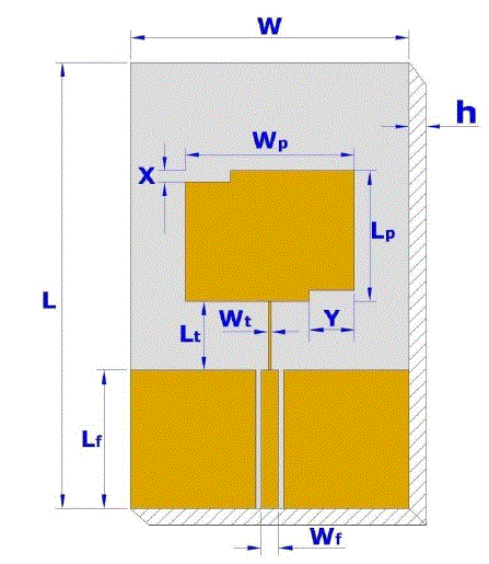
| Figure 1 shows the top view geometry of two corners truncated unipolar rectangular microstrip antenna (TCTURMSA). In Fig.1 the area of the substrate is L ïÃâô W cm. On the top surface of the substrate a ground plane of height which is equal to the length of microstripline feed Lf is used on either sides of the microstripline with a gap of 0.1 cm desired gap is maintained between microstripline feed and top ground plane. However gap is maintained as small as possible for better coupling effect. The value lesser than 0.1 cm is difficult to fabricate practically and hence it has been chosen as 0.1 cm. On the bottom of the substrate a continuous ground copper layer of height Lf is used below the microstripline. The TCTURMSA is designed for 3 GHz of frequency using the equations available for the design of conventional rectangular microstrip antenna in the literature [2]. The length and width of the rectangular patch are Lp and Wp respectively. The feed arrangement consists of quarter wave transformer of length Lt and width Wt which is connected as a matching network between the patch and the microstripline feed of length Lf and width Wf. A semi miniature-A (SMA) connector is used at the tip of the microstripline feed for feeding the microwave power. In Fig.1 two opposite corners of the radiating patch are truncated symmetrically with vertical and horizontal lengths X and Y. The values of X and Y are taken in terms of λo and these are equal to λo/50 and λo/12.34 respectively. |
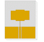
| Figure 2 shows the geometry of four corners truncated unipolar rectangular microstrip antenna (FCTURMSA). In this figure four corners of the rectangular radiating patch are truncated symmetrically with vertical and horizontal lengths of X and Y. The values of X, Y and the other geometry of Fig. 2 remain same as that of Fig.1. The design parameters of the proposed antenna is shown in Table 1 |
EXPERIMENTAL RESULTS
|
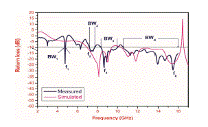
| The antenna bandwidth over return loss less than -10 dB is simulated using HFSS simulating software and then tested experimentally on Vector Network Analyzer (Rohde & Schwarz, Germany make ZVK model 1127.8651). The variation of return loss verses frequency of TCTURMSA is as shown in Fig. 3. From this graph the experimental bandwidth (BW) is calculated using the equations, |
 |
| were, f1 and f2 are the lower and upper cut of frequencies of the band respectively when its return loss reaches – 10 dB and fc is the centre frequency of the operating band. The variation of return loss verses frequency of TCTURMSA is as shown in Fig. 3. From this figure it is seen that, the antenna operates for four bands of frequencies BW1 to BW4. The magnitude of these operating bands measured at BW1 to BW4 is found to be 90 MHz (1.90 %), 540 GHz (7.27 %), 1.71 GHz (18.65 %) and 2.74 GHz (41.32 %) respectively. |
| The resonant mode f1 at 4.76 GHz is due to the fundamental resonant frequency of the patch and others modes f2 and f3 are due to the novel geometry of TCTURMSA. The multi mode response obtained is due to different surface currents on the patch. The fundamental resonant frequency mode f1 shifts from 3 GHz designed frequency to 4.76 GHz due to the coupling effect of microstripline feed and top ground plane of TCTURMSA. The simulated results of TCTURMSA is also shown in Fig. 3. The experimental and simulated results are in close agreement from BW2 to BW4. |
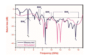
| The variation of return loss verses frequency of FCTURMSA is as shown in Fig. 4. From this figure it is seen that, the antenna operates for four bands of frequencies BW5 to BW8. The magnitude of these operating bands measured at BW5 to BW8 is found to be 150 MHz (3.12 %), 330 GHz (4.51 %), 1.66 GHz (18.16 %) and 2.76 GHz (41.84 %) respectively. The resonating modes f5, f6, f7 and f8 remain same when compared to f1, f2, f3 and f4 of Fig.3 of TCTURMSA. The highest impedance bandwidth of FCTURMSA is found at BW8 which is equal to 41.86 with minimum return loss of -32.97 dB. The simulated results of FCTURMSA is also shown in Fig. 4. The experimental and simulated results are in close agreement from BW6 to BW8. |
| The gain of the TCTURMSA and FCTURMSA is measured by absolute gain method. The power transmitted „PtâÃâ¬ÃŸ by pyramidal horn antenna and power received „PrâÃâ¬ÃŸ by antenna under test (AUT) are measured independently. With the help of these experimental data, the gain (G) dB of AUT is calculated by using the formula, |
 |
| where, Gt is the gain of the pyramidal horn antenna and R is the distance between the transmitting antenna and the AUT. Using equation (2). The maximum gain of proposed antennas measured in their operating bands BW1 to BW8 is tabulated in Table 2. From this table it evident that, the FCTURMSA is capable of giving lager gains in all operating bands when compared to the gain of TCTURMSA |
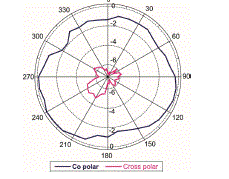
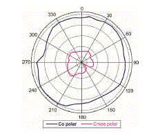
| The co-polar and cross-polar radiation pattern of TCTURMSA and FCTURMSA are measured at 4.76 GHz. The typical radiation patterns measured at 4.76 GHz are shown in Fig 5 to 6 respectively. The obtained patterns are ominidirectional in nature. The cross-polar power levels of proposed antennas are -4.69 and −5.72 dB respectively. The cross-polar power levels are down compared to co-polar power level. |
CONCLUSION
|
| From the detailed experimental study, it is concluded that, the TCTURMSA with microstripline feed have been designed for quad-band operation with a peak gain of 9.70 dB. The antenna operates for four bands of frequencies in the range of 4 to 16 GHz. If four corners of the patch are truncated symmetrically, the antenna operates again for four bands and also retains same resonant frequencies. The antenna shows enhancement of gain in all operating bands with ominidirectional radiation characteristics. The proposed antennas are simple in their structure and they use low cost substrate material FR4. With these features the proposed antennas may find applications in microwave communication systems operating in the frequency range of 4 to 16 GHz. |
ACKNOWLEDGEMENTZ
|
| The authors would like to thank Dept. of Sc. & Tech. (DST), Govt. of India. New Delhi, for sanctioning Vector Network Analyzer to this Department under FIST project. The authors also would like to thank the authorities of Aeronautical Development Establishment (ADE), DRDO Bangalore for providing their laboratory facility to make antenna measurements on Vector Network Analyzer. |
Tables at a glance
|
 |
 |
| Table 1 |
Table 2 |
|
| |
Figures at a glance
|
 |
 |
 |
| Figure 1 |
Figure 2 |
Figure 3 |
|
 |
 |
 |
| Figure 4 |
Figure 5 |
Figure 6 |
|
| |
References
|
- Constantine A. Balanis, Antenna theory analysis and design, John Wiley, New York, 1997.
- I. J. Bahl and P. Bharatia, Microstrip antennas, Dedham, MA: Artech House, New Delhi, 1981.
- K. C. Gupta and Abdelaziz Bernalla, Micostrip antenna design, Artech House, New Delhi, 1988.
- Jia- Yi Size, Kin-lu Wong, “Slotted rectangular microstip antenna for bandwidth enhancement”, IEEE Trans Antennas and Propagat vol. 48, no. 8, pp.1149-1152, 2000.
- K. Song, Y. Z. Yin, S. T Fan, Y. Z Wang and L. Zhang, “Open L-slot antenna with rotated rectangular patch for bandwidth enhancement”, Electron Lett. No. 45, no. 25, pp.1286 – 1288, 2009.
- M. John and M. J Ammann, “Optimization of impedance bandwidth for the printed rectangular monopole antenna”, Microwave Opt Technol Lett vol. 47, pp.153-154, (2005).
- K. P. Ray and Y. Ranga, Printed rectangular monopole antenna, Proc. IEEE APS Int. Symp. New Mexico, USA,1636-1639, 2006.
- C.C Liang. J. Chiau, Chem, and C. G. Parini, Printed circular disc monopole antenna for ultra wideband applications. Electron Lett, vol.40, no. 20, 1246-1248,2004.
- C. Y Huang and W.C. Hsia, Planar elliptical antenna for ultra wideband application, Electron Lett, vol.41, no. 6, 296 – 297, 2005.
- C. C. Lin, Y. C. Kan, L. C. Kuo and H. R Chuang, A planar triangular monopole antenna for UWB communication, IEEE Microwave and Wireless components Lett, vol. 15, no. 10, 624-626, 2005.
- K. P. Ray and Y. Ranga, Ultra wideband printed modified triangular monopole antenna. Electron Lett, vol. 42, no. 19, 1081- 1082, 2006.
- K. P. Ray Y. Ranga and P. Gabhale, Printed square monopole antenna with semicircular base for ultra-wide bandwidth, Electron Lett, vol.43, no. 5, 263-265, 2007.
|
