Keywords
|
| micro grids , droop control, power sharing, parallel inverter. |
INTRODUCTION
|
| Rapidly increasing energy demand from the industrial and commercial sector, especially in the current climate of high oil prices, steadily reducing energy sources and at the same time increased concerns about environmental changes, have caused fast development of Distributed Power Generation Systems (DPGS) based on renewable energy. A recent concept is to group DPGS and the associated loads to a common local area forming a small power system called a microgrid. Furthermore, the improvement of the control capabilities and operational features of microgrids brings environmental and economic benefits. The introduction of microgrids improves power quality, reduces transmission line congestion, decreases emission and energy losses, and effectively facilitates the utilisation of renewable energy resources. As nonlinear and/or unbalanced loads can represent a high proportion of the total load in small-scale systems, the power quality is major problem in microgrids[1]. The microsources for MicroGrids are small (<100-kW) units with powerelectronic interfaces. These sources (typically microturbines, PV panels, and fuel cells) are placed at customers sites. Most of the DERs need power electronics interfaces to be connected to the microgrid [2-6]. Consequently, inverters orac-dc-ac converters are adopted to connect the DERs to thelocal ac bus inorder to share loads properly. For the onsite distributed generation , communication wireinterconnections are usually uneconomic, and the system reliability is degraded due to those long distancecommunication wires. As a result, lots of wireless controlstrategies based on the droop method are developed [7-9]. For inverter-based autonomous microgrid, the droop control is widely used to regulate the power flow according to the local information without requiring any communication. An ideal droop control should provide the fast and accurate power sharing without affecting the voltage and frequency at the point of common coupling (PCC). |
| The conventional droop control only takes the inverter output inductance into account and the resistance of the filter inductor is usually ignored. However, the ESR have a great impact the power sharing accuracy of the inverters. The line impedance which contains both resistance and inductance also contributes a large part to the total impedance of the inverter. In the low voltage microgrids the resistance may even take the main part of the line impedance [9]. An orthogonal transform of the active and reactive power of the inverter is taken to eliminate the impact of the resistance and keep the decoupling characteristic of the active and reactive power [7]. Many of the droop control methods take the active and reactive power as the control variables [11, 12], which might cause current spikes during the initial and transient states or surge current during grid fault. In [7], the active and reactive current is taken as the control variables, and thus the current spikes could be limited. For conventional droop control, the transient response and power sharing accuracy are determined by the droop coefficients. Unfortunately, the dynamic response and power sharing accuracy is not satisfied when only using the simple frequency and voltage droop control [8]. In this paper, an improved droop control strategy isproposed to enhance the dynamic performance of the parallel inverters in microgrids without communication wireinterconnections. A wireless controller is developed by taking the active and reactive current as the control variables, an orthogonal transform of the control variables is taken for decoupled control inorder to ensure the power sharing accuracy, and additional terms are added to the droop controller to enhance the dynamic performance. Simulation results and waveforms are given to validate the proposed control strategy. |
STRUCTURE OF MICROGRID
|
| A typical microgrid is shown in Fig. 1, which includes PV panels, wind turbines, batteries, super capacitors, electrochemical storage and micro turbines. Since most of the micro sources are DC form or need to be converted to DC form first, voltage source inverters are most significant for each of the micro sources. The inverters can be modelled as a voltage source connected to the ac bus through complex impedance. Parallel inverters are the basic aspects of microgrids. |
REVIEW OF CONVENTIONAL DROOP CONTROL
|
| The power droop control has a long history of use for the synchronous generator control in power system. Recently, it has been used for parallel inverter control, especially in inverter based microgrids . |
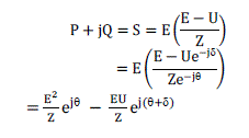
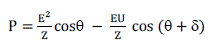
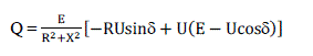
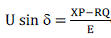
| The impedance of the intermediate transmission line be Z and injected power is S = P + jQ. Here P is the real power, Q is the reactive power and E and U are the magnitude of output voltage. The following will provide a brief review of the conventional power droop scheme. |
 |
 |
 |
 |
 |
 |
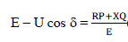 |
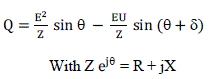
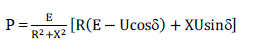
| For overhead lines XR, which means that R may be neglected. If also the power angle is small, then sin = and cos = 1.Equations (6) and (7) then become |
 |
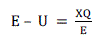 |
| In other words, the active power is moredependent on the power angle (frequency) variation, whilethe reactive power Qis more sensitive to variation in the magnitude of output voltage. That is why P-F and Q-V droop controlschemes are widely used in power systems. At the same time, changing frequency causes dynamic change of the phase error δ. Consequently, the conventional droop control method is developed based on the decoupled control of the active power and reactive power via output frequency and voltage amplitude. |
 |
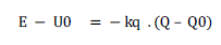 |
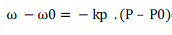
| In (10) and (11), ω0 and U0 are the inverter output angular frequency and voltage amplitude without load, P0 and Q0 arethe reference of the active and reactive power, kp and kqare the droop coefficients for the frequency and voltage amplitude, respectively. For a given operation point, only two droop coefficients kp and kqcan be adjusted to change the power sharing accuracy and dynamic response of the conventional droop control, and the resistance of the inverter output impedance or line impedance is ignored which must be considered under low voltage microgrids conditions.The frequency and voltage droop control characteristics are shown graphically in Fig. 3. The conventional droop control works well only under the assumption that the line impedance is mainly inductive. Therefore, the conventional droop control method needs to be improved for microgrids applications. |
PROPOSED CONTROL STRATEGY
|
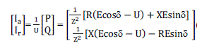
| Instead of active and reactive power , Active current and reactive current are obtained in (7) as the control variables in order to reduce the current spikes due to the initial phase error or grid fault. |
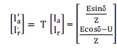
| In low voltage microgrids, the line resistance can’t be ignored, because the R/X ratioof the transmission line is relatively high as shown in Table 1. In this case, the conventional power droop control might suffer from the poor power decoupling and power sharing. Therefore, the active and reactive currents are coupled by line resistance and inductance. An orthogonal transform is taken to obtain the decoupled control variables as given by (8). It can be seen that the new control variables Ia’ is proportional to the inverter output voltage phase error δ and Ir’is proportional to amplitude E when δ is small. As mentioned in part III, the conventional droop control method presents a decoupled characteristic between P, Q and δ, E at the expense of ignoring the line resistance. The proposed strategy decouples Ia’ and Ir’ with consideration of the line resistance, therefore, it is suitable for microgrid application. |
 |
 |
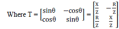 |
| The proposed control is shown graphically in Fig. 4, Ia0’ and Ir0’ are the transformed active and reactive currentreference, ω0 and U0 are the inverter output angular frequency and voltage amplitude without load, Vref is the inverter output voltage reference which is synthesized by ω and E. Three phase instantaneous power theory [13] is used to calculate the inverter output active power P and reactive power Q. The matrix T is the orthogonal transformation for decoupled control in (14). The droop functions of the proposed strategy are given by (15) and (16). |
 |
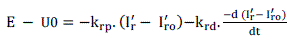 |
| As illustrated, the proposed droop control strategy takes the transformed active current Ia’ and reactive current Ir’ as the control variables, and integral – derivative terms are added to the droop functions to enhance the dynamic response of the inverters. This is shown graphically in Fig. 4. The coefficients of the proposed controller can be designed by calculating the small signal function of δ through (14)ïýÞ(16), and using root locus method to observe the impact of these coefficients over the system dynamics. |
| The overall diagram of the proposed control scheme using in three phase voltage source inverter applications is givengraphically in Fig. 5. As seen, only the inverter output voltage uabc and output current iabcwhich are locally measurable are using to implement the proposed control scheme. The control scheme can be implemented where the feedback information are converted to digital values first and power calculation is done. Then the transformed active and reactive current are calculated to realize the droop control algorithm and power sharing control, finally the PWM driving signals are produced through the inner voltage regulation control. |
SIMULATION RESULTS
|
| Parallel connected voltage source inverters are basic elements in microgrids. Therefore, two parallel connected three phase inverters system is designed as shown in Fig. 6, the load is connected to the common ac bus of the two inverters. To validate the proposed control scheme, simulations are carried out based on this configuration with the proposed control scheme. Simulation is done using MATLAB/SIMULINK. |
| Simulation results of the dynamic response of two parallel inverters are given in Fig.8 to show the validity of the proposed control strategy. In Fig. 8 i), inverter 1 and inverter 2 are parallel connected and running with a 20kW load, and the common linear load is reduced by 10kW at 0.08s. In Fig. 8 ii) the inverters first running at 10kW and the common load is increased to 20kW in 0.8s. In Fig 9 the dynamic response of the inverters with nonlinear load is shown. The simulation result shows that the parallel connected inverters can properly share its half of the load within one cycle. The circulating current i1-i2is small when the system settles to the steady state. The current spikes are greatly reduced and have better THD. |
CONCLUSION
|
| This paper proposes an improved droop control strategy for parallel inverters in microgrids. Resistance of the inverter output impedance and line impedance are considered for power sharing accuracy. An orthogonal transformation is applied for decoupled active and reactive current control. The current spikes are reduced by controlling the real and reactive power. Furthermore, derivative and integral terms are added into the droop functions to enhance the dynamic performance of the inverters. Simulation results and waveforms are given validate the effectiveness of theproposed control strategy. |
Tables at a glance
|
 |
| Table 1 |
|
| |
Figures at a glance
|
 |
 |
 |
 |
 |
| Figure 1 |
Figure 2 |
Figure 3 |
Figure 4 |
Figure 5 |
|
 |
 |
 |
 |
| Figure 6 |
Figure 7 |
Figure 8 |
Figure 9 |
|
| |
References
|
- H. Nikkhajoei and R. H. Lasseter, "Distributed Generation Interface to the CERTS Microgrid," Power Delivery, IEEE Transactions on, vol. 24, pp. 1598-1608, 2009.
- R. H. Lasseter, "Microgrids," in Power Engineering Society Winter Meeting, 2002. IEEE, 2002, pp. 305-308 vol.1.
- N. Hatziargyriou, et al., "Microgrids," Power and Energy Magazine, IEEE, vol. 5, pp. 78-94, 2007.
- E. Bark Lund, et al., "Energy Management in Autonomous Microgrid Using Stability-Constrained Droop Control of Inverters," PowerElectronics, IEEE Transactions on, vol. 23, pp. 2346-2352, 2008.
- J. M. Carrasco, et al., "Power-Electronic Systems for the Grid Integration of Renewable Energy Sources: A Survey," Industrial Electronics, IEEETransactions on, vol. 53, pp. 1002-1016, 2006.
- F. Blaabjerg, et al., "Overview of Control and Grid Synchronization for Distributed Power Generation Systems," Industrial Electronics, IEEETransactions on, vol. 53, pp. 1398-1409, 2006.
- K. De Brabandere, et al., "A Voltage and Frequency Droop Control Method for Parallel Inverters,"Power Electronics, IEEE Transactions on, vol. 22, pp. 1107-1115, 2007.
- J. M. Guerrero, et al., "A wireless controller to enhance dynamic performance of parallel inverters in distributed generation systems," Power Electronics, IEEE Transactions on, vol. 19, pp. 1205-1213, 2004.
- J. M. Guerrero, et al., "Wireless-Control Strategy for Parallel Operation of Distributed-Generation Inverters," Industrial Electronics, IEEETransactions on, vol. 53, pp. 1461-1470, 2006.
- R. M. Wright, "Understanding modern generator control," Energy Conversion, IEEE Transactions on, vol. 4, pp. 453-458, 1989.
- J. C. Vasquez, et al., "Adaptive Droop Control Applied to Voltage- Source Inverters Operating in Grid-Connected and Islanded Modes," Industrial Electronics, IEEE Transactions on, vol. 56, pp. 4088-4096, 2009.
- Y. Mohamed and E. F. El-Saadany, "Adaptive Decentralized Droop Controller to Preserve Power Sharing Stability of Paralleled Inverters in Distributed Generation Microgrids," Power Electronics, IEEETransactions on, vol. 23, pp. 2806-2816, 2008.
- H. Akagi, et al., "Instantaneous Reactive Power Compensators Comprising Switching Devices without Energy Storage Components," Industry Applications, IEEE Transactions on, vol. IA-20, pp. 625-630, 1984.
- J. M. Guerrero, J. Matas, L. G. de Vicuna, M. Castilla, and J. Miret, “Decentralized control for parallel operation of distributed generation inverters using resistive output impedance,” IEEE Transactions on Industrial Electronics, vol. 54, no. 2, pp. 994–1004, 2007.
- J. M. Guerrero, J. C. V´asquez, J. Matas, M. Castilla, and L. G. Vicuna, “Control strategy forflexible microgrid based on parallel line-interactive UPS systems,” IEEE Transactions onIndustrial Electronics, vol. 56, no. 3, pp. 726–736, 2009.
|