International Journal of Advanced Research in Electrical, Electronics and Instrumentation Engineering
ISSN ONLINE(2278-8875) PRINT (2320-3765)
ISSN ONLINE(2278-8875) PRINT (2320-3765)
Amanpreet Kaur1, Rishikesh Pandey2
|
| Related article at Pubmed, Scholar Google |
Visit for more related articles at International Journal of Advanced Research in Electrical, Electronics and Instrumentation Engineering
The paper presents current adder and subtractor circuits based on cascode current mirror with improved linearity and wide linear range. The proposed circuits can be used for analog signal processing applications such as amplifiers, operational transconductance amplifiers (OTA), Gm-C filters, etc. In the proposed circuits, cascode current mirror topology is employed to improve current mirroring operation. The proposed circuits have been simulated using TSMC 0.18μm CMOS process technology with a supply voltage of 1.8 V. The proposed circuits operate efficiently within the current range of 0 to 80μA with the permissible error percentage of less than 2.5%. The SPICE simulation results have been presented to demonstrate the effectiveness of the proposed circuits
Keywords |
||||||||
| Adaptive biasing, cascode current mirror, current mode circuits, adder, subtractor. | ||||||||
INTRODUCTION |
||||||||
| In low-voltage/ low-power analog systems, current-mode signal processing has been usually considered an attractive strategy due to its potential for high-speed operation and low-voltage compatibility [1]-[4]. The behaviour of electrical circuits is always the result of interplay between voltage and current. In current mode circuits (CMCs), the currents determine the complete circuit response. The voltage signals are irrelevant in determining the circuit performance. Current-mode circuit (CMC) techniques which process the active signals in the current domain have simple architectures. The CMCs are suitable for integration in CMOS technology as they do not require specially processed capacitors or resistors and hence, they are more compatible with digital CMOS technology making integration of mixed signal circuits more feasible. In a current mode circuit, a change in current level is not necessarily accompanied by a change in the voltage level. Hence, the parasitic capacitances do not affect the operating speed of the circuit by a significant amount [5]. Therefore many conventional voltage mode circuit topologies have been replaced by new and innovative current mode designs because current mode approach proves a better alternative for low voltage high performance analog circuitdesign in which the circuit designer is more concerned with current levels for the operation of the circuits. | ||||||||
BACKGROUD |
||||||||
| The current mirrors (CMs) are one of the basic building blocks of current mode circuits which are used in analog signal processing cells [3], [6]-[10]. These are used as biasing structures or constant current sources and as an active load in amplifier stages since, it offer high impedance [11]-[12]. It is used to generate a replica of given reference current. It can also amplify or attenuate the reference current. Ideally, the output impedance of a current source/ sink should be infinite and capable of generating or drawing a constant current over a wide range of voltages. However, the finite value of output resistance and a limited output voltage required to keep device in saturation ultimately limits the performance of the current mirror [13]-[16]. Current mirror topology based analog circuits have simple structures and leads to easy implementation of operations such as addition and subtraction. | ||||||||
| Several authors have proposed current mode computational circuits in literature [17-19]. Ferri et al. [17] have proposed simple current mirror based current subtractor. In [18], a current subtractor using PMOS wide swing cascode current mirror has been suggested. Lin et al. [19] have proposed current subtractor based on flipped voltage follower cell. In this paper, we have proposed current mode computational circuits such as current subtractor and current adder based on NMOS cascode current mirror (CCM) topology with improved linearity. | ||||||||
| The paper is organized as follows: In Section II, the principles and architectures of the proposed current subtractor and adder based on CCM topology is described. The simulation results are presented in section III. The paper is concluded in section IV. | ||||||||
PROPOSED CURRENT ADDER AND CURRENT SUBTRACTOR CIRCUITS BASED ON NMOS CASCODE CURRENT MIRROR |
||||||||
| Current mirrors are one of the most important and widely used building blocks of analog architectures. Conventional current mirrors operate on the principle that if the gate-source voltage of the two identical MOS transistors is equal, then the drain currents should be equal [13]. The conventional current mirror is shown in Figure 1. | ||||||||
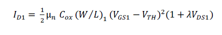
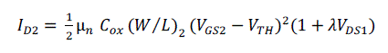
| The drain currents ID1 and ID2 of transistors M1 and M2, respectively, are given as | ||||||||
 |
||||||||
 |
||||||||
| whereμis the charge-carrier effective mobility, is the gate-oxide capacitance per unit area, are aspect ratios, ,are gate-source voltages,is threshold voltage, are drain-source voltages and is the channel length modulation parameter of transistors M1 and M2, respectively. | ||||||||
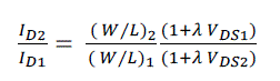
| Since, the transistor M1 is diode connected, the drain-source voltage of transistor M1 (VDS1)is equal to its gate-source voltage (VGS1).Also, gate terminals of both the transistors M1 and M2 are tied together, therefore gate-source voltages of M1 and M2 are equal (i.e.VGS1=VGS2). Using equations (1) and (2), the ratio of drain currents ID1 and ID2 is given as | ||||||||
 |
||||||||
| Since, VDS 1 ≠ VDS2, the drain currents of transistors M1 and M2 are not equal. Also, the effect of channel length modulation introduces the significant error in copying currents. To remove the drawback of channel length modulation effect in conventional current mirror, the idea of cascode structure is employed. Ability to suppress the channel length modulation effects in cascode current mirror (CCM) is achieved by making drain to source voltage of M1 and M2equal, so that output current (Iout) always follows the reference current (Iref). In addition to this, cascode structure increases output resistance to gmro 2 , where gm is the transconductance of the transistor. For implementing cascode current mirror structure, a cascode current source using NMOS transistor M3 is used, as shown in Figure 2. | ||||||||
| The bias voltage (Vb) of transistor M3 is chosen such that, voltage at node X (VX) is equal to voltage at node Y (VY). By applying KVL in the loop consisting transistors M3 and M2 to ground, considering their respective gate voltages and voltage at node Y w.r.t ground, the voltage VY is given as | ||||||||
| From equation (4) it can be seen that if gate- source voltage is added to voltage at node X (VX), then the required value of Vb can be obtained. Hence, another diode connected device M4 is placed in series with M1 as shown in Figure 3, thereby generating a voltage at node N (VN) which is given as | ||||||||
| Connecting node N to the gate of transistor M3, as shown in Figure 4, the voltage at node N is given as, | ||||||||
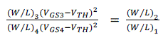
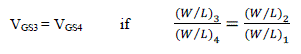
| From equation (6), it is observed that for VX to be equal to be equal to VY, VGS3 and VGS4 has to be equal. The ratio of drain currents of transistors M1, M2 and M3, M4 are given as | ||||||||
| Since VGS1= VGS2, equation (7) is modified as | ||||||||
 |
||||||||
| Now equation (8) reduces to | ||||||||
 |
||||||||
| Using equations (6) and (9), the voltage VY is given as | ||||||||
| Hence, the drain currents of transistors M1and M2 become equal (i.e. ID2 = ID1 or Iout = Iref). | ||||||||
(A) Proposed Current Adder Circuit based on CCM |
||||||||
| The proposed current adder using NMOS type cascode current mirror is shown in Figure 5. All the transistors are biased in saturation region and the transistors M1-M2, M3-M4, M5-6, and M7-M8 are perfectly matched. The cascode current mirrors are developed using transistors M1-M4 and M5-M8 whose function is to precisely copy the input currents AIin1 and AIin2, in transistor M4 and M8, respectively. | ||||||||
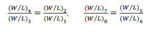
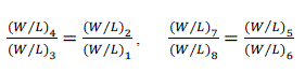
| The current AIin1and Ain2is copied in transistors M2,M4 and M8,M9 by cascode current mirrors formed by transistors M1-M4 and M5-M8.For achieving the proper biasing voltage of cascode structure, the aspect ratios of transistors are chosen as, | ||||||||
 |
||||||||
| Applying KCL at node X, the output current Io is given as | ||||||||
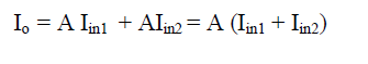 |
||||||||
| From equation (12), it can be seen that the output current is the addition of two input currents AIin1 and AIin2, where A is the gain factor. | ||||||||
(B) Proposed Current Subtractor Circuit based on CCM |
||||||||
| Using the same topology of CCM, the current subtractor is also proposed which is shown in Figure 6. The cascode current mirrors are implemented by using NMOS transistors as active elements. All the transistors are biased in saturation mode and the transistors pairs M1-M2, M3-M4, M5-6, and M7-M8 are perfectly matched. The transistors M1-M4 and M5-M8 are arranged in cascode current mirror topology in which transistors pairs M1, M3 and M6, M8 are configured as diode connected to operate them in saturation region. | ||||||||
| The current Iin1 is copied in transistors M2 and M4 by the cascode current mirror formed by transistors M1-M4.Another cascode current mirror is formed by transistors M5-M8 which mirrors the output current i.e. the subtraction of two currents. For the proper biasing voltage of cascode structure the aspect ratio of transistors are chosen as, | ||||||||
 |
||||||||
| From Figure 6, it can be seen that current Iin1 through transistors M1, M3 is copied accurately in transistors M2, M4 (i.e. I (M4, M2) = Iin1). | ||||||||
| By applying KCL at node X, the current IX is given as | ||||||||
| Therefore, the output current Io is given as | ||||||||
| From equation (15), it can be seen that the output current is the subtraction of two input currents AI1 and AI2, where A is the gain factor. The proposed current subtractor circuit find wide application in adaptive biasing of amplifiers. | ||||||||
SIMULATION RESULTS AND DISCUSSION |
||||||||
| The proposed circuits have been simulated in TSMC 0.18μm CMOS process technology. The proposed computational circuits have been designed to operate within the current range of 0 to 80μA. The DC characteristics of the proposed current adder (Figure 5) is shown in Figure 7, in which output current varies from 10 μA to 90 μA w.r.t input current variation from 0 μA to 80μA and keeping one of the current sources fixed at 10 μA.Table I shows the comparison of theoretical and simulated values of output current. From the Table I, it can be seen that the percentage error between theoretical and simulated output current is less the 0.025%. | ||||||||
| From Figure7 it can be observed that the proposed current adder circuit shows good linearity response over a wide range of current. The improved linearity characteristics are attributed to the use of cascode current mirror topology which provides precise copying of the currents by eliminating the channel length modulation effect in conventional current mirrors. Table I shows the comparison of theoretical and simulated values of output current. | ||||||||
| The DC characteristics of current subtractor (Figure 6) is shown in Figure 8 ,in which output current varies from 80 μA to 0 μA w.r.t input current variation from 0 μA to 80 μA and keeping one of current sources fixed at 80 μA. Table IIshows the comparison of theoretical and simulated values of output current. From Table II, it can be seen that the % error in theoretical and simulated output current is less the 2.50% | ||||||||
| From Figure 8 , it can be observed that DC characteristics of the proposed current subtractor are linear over appreciable range of input current, hence the subtraction of two currents at the output is achieved with good accuracy. Thus the current subtractor designed with cascode current mirror topology can be employed in adaptive biasing of amplifiers. Table II shows the comparison of theoretical and simulated values of output current, one of the input current is fixed to a value while the other current source is varied and output current is subtraction of the two input currents. | ||||||||
CONCLUSION |
||||||||
| The proposed computational circuits for addition and subtraction operation have been developed using TSMC 0.18μm CMOS process technology. The proposed current subtractor and adder circuits have wide operating range of current of 0 to 80μA. The SPICE simulation results show that the proposed circuits have a good linearity response over a wide range of current. These circuits are useful for various analog signal processing applications such asamplifiers, operational transconductance amplifiers (OTA), Gm-C filters,etc. | ||||||||
ACKNOWLEDGEMENT |
||||||||
| We would like to sincerely thank the ECE department of Thapar University, Patiala for their continuous support and guidance during the course of this work. | ||||||||
Figures at a glance |
||||||||
|
||||||||
|
||||||||
References |
||||||||
|


