Humans communicate mainly by vision and sound; therefore, a man-machine interface would be more intuitive if it made greater use of vision and audio recognition. Another advantage is that the user not only can communicate from a distance, but need have no physical contact with the computer. However, unlike audio commands, a visual system would be preferable in noisy environments or in situations where sound would cause a disturbance. Gesture recognition can be seen as a way for computers to begin to understand human body language, thus building a richer bridge between machines and humans than primitive text user interfaces or even GUIs (graphical user interfaces), which still limit the majority of input to mouse. In this paper, we have identified an alternative to mouse command especially with reference to cursor controlling applications. The two application case scenario; one by hand gestures and another by hands-free interface i.e. Face gesture is discussed with algorithms used such as convex hull, Support vector machine and basic mathematical computation. They have been applied to give command and perform the activities like open any note pad, office tools software not by using mouse but by using gestures. The system when tested with different persons gestures and lightning conditions is giving reasonable results in identification and tracking of gestures/ gestures element. Then those identified gestures are applied to application designed. At last, the results obtained convey us that there is a good alternative to mouse that is by using gestures.
Key words |
| Gestures, Convex hull, Support Vector Machine. |
Introduction |
| The current evolution of computer technology has envisaged advanced machinery world, where in human life is
enhanced by artificial intelligence. Indeed, this trend has already prompted an active development in machine
intelligence, Computer vision, HCI for example, aims to duplicate human vision. Computer is used by almost all people
either at their work or in their spare-time. Special input and output devices have been designed over the years with the
purpose of easing the communication between computers and humans, the two most known are the keyboard and
mouse. Every new device can be seen as an attempt to make the computer more intelligent and making humans able to
perform more complicated communication with the computer. This has been possible due to the result oriented efforts
made by computer professionals for creating successful human computer interfaces. |
| Human–computer interaction (HCI) is the study, planning and design of the interaction between people (users) and
computers. It is often regarded as the intersection of computer science, behavioural sciences, design and several other
fields of study. Interaction between users and computers occurs at the user interface, which includes both software and
hardware; for example, characters or objects displayed by software on a personal computer's monitor, input received
from users via hardware peripherals such as keyboards and mouse, and other user interactions with large-scale
computerized systems such as aircraft and power plants. So this paper mainly focuses on an alternative mode of
communication through hand/face gestures. This paper is organized as follows. The next section gives brief
background of cursor controlling application through gestures followed by two case studies; one dealing with hand
gestures and other through face gestures with their architecture, methods/algorithms and implementation details.
Results are discussed from both application point of view followed by conclusion of study. |
MOTIVATION AND BACKGROUND |
| There is no submission or publication fee. Humans communicate mainly by vision and sound, therefore, a manmachine
interface would be more intuitive if it made greater use of vision and audio recognition [1]. Another advantage
is that the user not only can communicate from a distance, but need have no physical contact with the computer.
However, unlike audio commands, a visual system would be preferable in noisy environments or in situations where
sound would cause a disturbance. Gesture recognition can be seen as a way for computers to begin to understand
human body language, thus building a richer bridge between machines and humans than primitive text user interfaces
or even GUIs (graphical user interfaces), which still limit the majority of input to mouse. The clicking method was
based on image density, and required the user to hold the mouse cursor on the desired spot for a short period of time. A
click of the mouse button was implemented by defining a screen such that a click occurred [1], [2], [3]. Reference [5]
used only the finger-tips to control the mouse cursor and click. So here we are presenting two application cases with
reference to cursor control of computer system with two different aspects of gestures. One with using „Hands Interface‟
and another with „Hands-free Interface ' in HCI which is an assistive technology that is intended mainly for the use of
the disabled. |
| In hands- Interface application, its highlight the cursor controlling through the hand gestures without the use of mouse/
keyboard but performing the similar activity by using hand gestures. The hand-free interface will help them use their
voluntary movements, like head movements, to control computers and communicate through customized educational
software or expression building programs. One way to achieve that is to capture the desired feature with a webcam and
monitor its action in order to translate it to some events that communicate with the computer. In our application we are
using facial features to interact with the computer. The nose tip is selected as the pointing device; the reason behind
that decision is the location and shape of the nose; as it is located in the middle of the face it is more comfortable to use
it as the feature that moves the mouse pointer and defines its coordinates. Eyes were used to simulate mouse clicks, so
the user can fire their events as he blinks. It will help them use their voluntary movements, like head movements; to
control computers and communicate through customized educational software or expression building programs. People
with severe disabilities can also benefit from computer access to take part in recreational activities, use the Internet or
play games. This system can also be chosen to test the applicability of „Hands-free Interface‟ to gaming, as it is an
extremely popular application on personal computers. |
| The aim of this work is to enable users to interact more naturally with their computer by simple hand /face gestures to
move the mouse and perform tasks. Anyone acquainted with a computer and a camera should be able to take full
advantage of this work. |
APPLICATION CASE STUDY – I : CURSOR CONTROL COMMUNICATION MODE THROUGH HAND GESTURES |
A. Introduction |
| Hand gestures play a vital role in gestures recognition. This section highlight about the usage of hand gestures in
controlling the computer system by performing simple command without the use of traditional controlling device mode
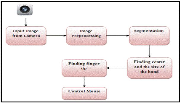
such as either of mouse or keyboard. In this system, first the input image is captured and after pre-processing on it is
converted to a binary image to separate hand from the background. Then centre of hand is calculated and computed
calculated radius of the hand is found. Fingertip points are been calculated using the Convex Hull algorithm. All the
mouse movements are controlled using the hand gesture. |
| Once we get an image from the camera, the image is converted to YCbCr from the color space RGB as shown in fig. 1.
Then, we define a range of colors as „skin color‟ and convert these pixels to white; all other pixels are converted to
black. Then, the centric of the dorsal region of the hand is computed. Once the hand is identified, we find the circle that
best fits this region and multiply the radius of this circle by some value to obtain the maximum extent of a „non-finger
region‟. From the binary image of the hand, we get vertices of the convex hull of each finger. From the vertex and
canter distance, we obtain the positions of the active fingers. Then by extending any one vertex, we control the mouse
movement. |
| To recognize that a finger is inside of the palm area or not, we have used a convex hull algorithm. Basically, the convex
hull algorithm is used to solve the problem of finding the biggest polygon including all vertices. Using this feature of
this algorithm, we can detect finger tips on the hand. We will use this algorithm to recognize if a finger is folded or not.
To recognize those states, we multiplied 2 times to the hand radius value and check the distance between the center and
a pixel which is in convex hull set. If the distance is longer than the radius of the hand, then a finger is spread. In
addition, if two or more interesting points existed in the result, then we treat the longest vertex as the index finger and
the hand gesture is clicked when the number of the result vertex is two or more. The result of convex hull algorithm has
a set of vertexes which includes all vertexes. Thus sometimes a vertex is placed near other vertexes. This case occurs
on the corner of the finger tip. To solve this problem, we deleted a vertex whose distance is less than 10 pixels when
comparing with the next vertex. Finally, we can get one interesting point on each finger |
B. Algorithm Used |
| A convex hull algorithm for Hand detection and gesture recognition is used in many helpful applications. As the skin
color can be much efficiently differentiated in the YCrCb Color Model so this model is preferable than RGB and HSV.
For a more efficient detection, implementation of a background subtraction algorithm is used to differentiate between
skin like objects and real skin colors. Initially, a frame is captured with only the background in the scene, after that, for
every captured frame, each pixel in the new frame is compared to its corresponding one in the initial frame, if they pass
a certain threshold according to specific algorithm computations, then this pixel is considered from the human body and
it will be drawn in a new frame with its original color. If this pixel is below the threshold, then those two pixels are
considered the same and they are considered as background so the corresponding pixel will take a zero color in the
third frame. After repeating this for all frames' pixels, now we will have a new frame with only a human appearing in it,
and all the background took a color of zero. |
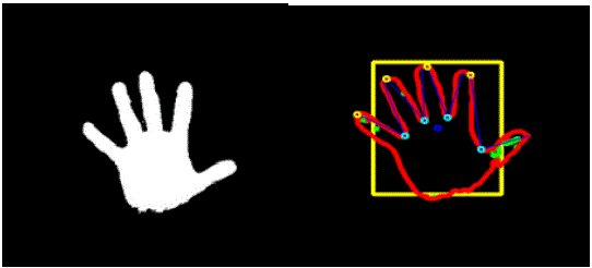
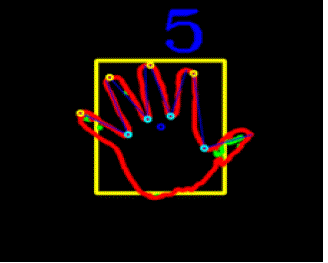
| Now we are having the detected hand as shown in fig. 2 and fig. 3, we have applied on this hand object an efficient
gesture recognition algorithm, that draws a convex hull over the hand object, and counts the number of defects in this
hull, if no defects found, then it is a closed hand, if five defects found, then there are five fingers waving, and so on. |
C. GUI and Implementation Details |
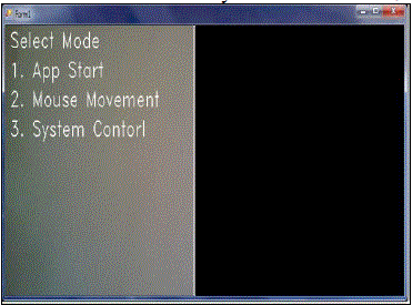
| We have implemented this application using OpenCV libraries [6, 7]. In GUI, we have provided three command modes
as shown in fig. 4. The command used is as briefly described below: |
| o Application Start Mode – It is used to start or run various applications such as, Notepad, Microsoft Word
and Command Prompt, etc. |
| o Mouse Movement Mode – This mode supports mouse operations, for example Double Click, Right Click
and Cursor Movement, etc. |
| o System Control Mode – It is used to control the system Shut Down, Log Off and System Restart activities. |
APPLICATION CASE STUDY – II : CURSOR CONTROL COMMUNICATION MODE THROUGH HANDS-FREE
GESTURES |
A. Introduction |
| In this scenario we are presenting the application to control the computer system thorough face gestures. Here we have
used Support Vector Machine (SVM). |
| The Support Vector Machines (SVMs) [11] are a popular machine learning method for classification, regression, and
other learning tasks. It is a new type of maximum margin classifiers. LIBSVM is a package developed as a library for
support vector machines. Thus LIBSVM is a library for Support Vector Machines (SVMs).The face detection process
uses this database for template matching. Libsvm stores all the necessary information in the “model” file that is created
from training. It knows what kernel and parameters to use. You only need to supply the model file and the test data.
Support Vector Machine (SVM) models are a close cousin to classical multilayer perceptron neural networks. Using a
kernel function, SVM‟s are an alternative training method for polynomial, radial basis function and multi-layer perceptron classifiers in which the weights of the network are found by solving a quadratic programming problem with
linear constraints, rather than by solving a non-convex, unconstrained minimization problem as in standard neural
network training. In the parlance of SVM literature, a predictor variable is called an attribute, and a transformed
attribute that is used to define the hyperplane is called a feature. The task of choosing the most suitable representation
is known as feature selection. A set of features that describes one case (i.e., a row of predictor values) is called a vector.
So the goal of SVM modeling is to find the optimal hyper plane that separates clusters of vector in such a way that
cases with one category of the target variable are on one side of the plane and cases with the other category are on the
other size of the plane. SVM takes as an input training data samples, where each sample consists of attributes and a
class label (positive or negative). The vectors near the hyper plane are the support vectors or in other words the data
samples that are closest to the hyper plane are called support vectors. |
B. Basic Terminologies used |
| Following gives the basic terminologies used in the algorithms |
| 1) SSR Filter : |
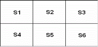
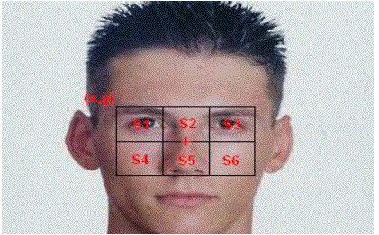
| SSR Filter stands for: Six Segmented Rectangular filters [12] which is as shown in fig. 5 |
| The sum of pixels2 in each sector is denoted as S along with the sector number. |
| 2) Integral Image : |
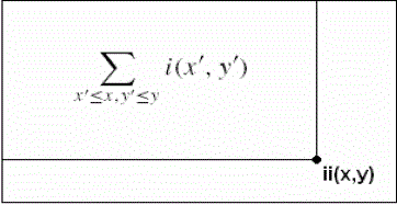
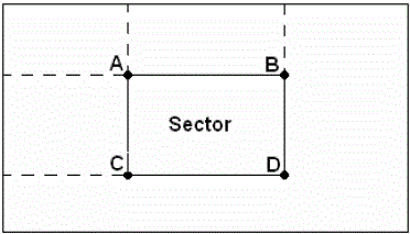
| In order to facilitate the use of SSR filters an intermediate image representation called integral image is used as
shown in fig. 6 In this representation the integral image at location x, y contains the sum of pixels which are above and
to the left of the pixel x, y. and its calculation of no of pixels in each sector is shown in fig. 7. |
| 3) SVM: |
| SVM takes as an input training data samples, where each sample consists of attributes and a class label (positive or
negative). The data samples that are closest to the hyper plane are called support vectors. The hyper plane is defined by
balancing its distance between positive and negative support vectors in order to get the maximal margin of the training
data set. We have use the SVM to verify the „between the eyes‟ template. |
| 4) Skin Color Model: |
| The human skin pixel value will range between particular fixed values. To find the skin color model 735 skin pixel
samples were extracted from each of 771 face images which were taken from a database. From these samples the
threshold value for skin pixel is set to identify whether a pixel is skin pixel or not. |
C. Face Detection Algorithm used |
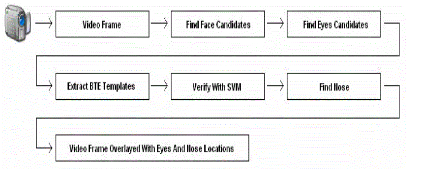
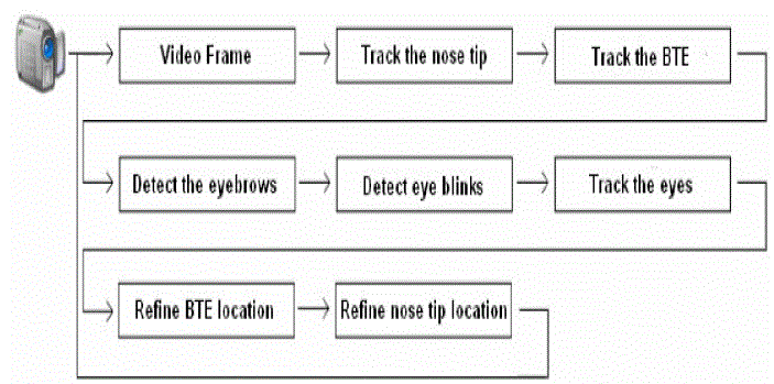
| A good face detection mechanism is discussed in [8], [9], [10] and [12]. The overview of it is depicted in fig. 8 |
| With reference to above, the main algorithmic flow is described below: |
| 1) Find Face Candidates: |
| To find face candidates the SSR filter will be used in the following way, also shown in fig. 9: |
| 1.1 Calculate the integral image by making a one pass over the video frame using the equations: |
| s(x,y) =a(x,y-1) + i(x,y) |
| ii(x,y)=ii(x-1,y) + s(x,y) |
| 1.2 Place upper left corner of SSR filter on each pixel of image only on pixels where the filter falls entirely inside the bounds of image. |
| 1.3 Place SSR filter, so that in ideal position the eyes fall in sectors S1 and S3, while the nose falls in sector S5 as shown in Fig 9. |
| 1.4 For each location check the conditions by the equations: |
| S1<S2 |
| S2>S3 |
| S1 < S4 && S3 < S6 |
| 1.5 The center of filter will be considered as face candidate if conditions are fulfilled. |
| 2) Cluster Face Candidates: |
| The clustering algorithm used is as follows: |
| 2.1 Passing the image from the upper left corner to the lower right one; for each face candidate fc: |
| · If all neighbors are not face candidates assign a new label to fc. |
| · If one of the neighbors is a face candidate assign its label to fc. |
| · If several neighbors are face candidates assign label of one of them to fc and make a note that the labels are
equal. |
| 2.2 After making the first pass we will do another one to assign to each group of equal labels a unique label, so the
final labels will become the clusters‟ labels. |
| 2.3 Set the centre of each cluster that is big enough with following equations: |
| x= [Σ x(i)]/n |
| y= [Σ y(i)]/n |
3) Find Pupils’ Candidates: |
| In order to extract BTE templates we need to locate pupils‟ candidates, so for each face candidates cluster: |
| 3.1 Center the SSR filter on the center of that cluster. |
| 3.2 Find pixels that belong to a dark area by binarizing the sector with a certain threshold. |
| 3.3 If the thresholding produces only one cluster, calculate the area of the part of the cluster which is in lower half of
the sector, if it is larger than a specified threshold then center of lower part is the pupil else the same will be
applied to upper half, otherwise omit the sector and no pupil is found. |
| 3.4 If there are multiple clusters: |
| - Find the cluster that is largest, darkest and closest to the darkest pixel of the sector.
-If either the left or right pupil candidate not found, skip the cluster. |
| 4) Extract BTE Templates: |
| After finding the pupils‟ candidates for each of the clusters the BTE templates are extracted in order to pass them to the
SVM. After extracting the template we scale it down with a particular scale rate, and we get a template that has the size
and alignments of the training templates. |
| 4.1 Find scale rate (SR) by dividing the distance between the left and right pupil candidates on 23 (distance between
left and right pupils in training templates). |
| 4.2 Extract a template of size 35*SR * 21*SR |
5) Classify Templates: |
| 5.1 Pass the extracted template to support vector machine. |
| 5.2 Multiply each of the positive results by the area of the cluster that its template represents. |
| 5.3 If all classification results are negative repeat the face detection process with a smaller SSR filter size. |
| 5.4 After selecting the highest result as the final detected face, the two pupils‟ candidates that were used to extract the
template that has that result will be set as the detected eyes. |
| 6) Find Nose Tip: |
| 6.1 Extract the region of interest (ROI). |
| 6.2 Locate nose-bridge-point (NBP) on ROI by using SSR filter having width as half of the distance between the
eyes. |
| 6.3 The center of the SSR filter is NBP candidate if center sector is brighter than the side sectors: |
| S2>S1 |
| S2>S3 |
7) Hough Transform : |
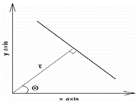
| Hough transform is used in our eyebrows detection algorithm. Suppose that we have a set of points, and we need to
find the line that passes as many of these points as possible. In Hough transform the line has two attributes: Θ and τ |
| To detect the line that passes from the set of points, steps in Hough transform algorithm are: |
| For each point in the set: |
| 1. Find the lines that pass from this point. |
| 2. Find the Θ and τ of each line. |
| 3. For each line: |
| o If it already exists (there is a line that has the same Θ and τ, and passes from another point) increase
its counter by 1. |
| o If it is a new line; create a new counter and assign the value 1 to it. |
| D. Face Tracking Algorithm used |
| 1) Setting Features ROI : |
| The location of the tracked feature in the past two frames (at moments t-1 and t-2) is used to predict its location in the
current frame (at moment t). To do so, calculate the shift value that the feature‟s template has made between frames t-2
and t-1, and shift the feature‟s ROI in the current frame from the feature‟s last place (in frame t-1) with that shift value.
The ROI location is set in a way that it stays entirely in the boundaries of the video frame. |
| 2) Template Matching: |
| The feature‟s new location is to be found in the ROI. A window that has the feature‟s template size is scanned over the
ROI and the SSD (Sum OF Squared Differences) between the template and the current window is calculated. After
scanning the entire ROI the window that has the smallest SSD is chosen as the template‟s match, and its location is
considered as the feature‟s new location. In order to achieve faster results; while calculating the SSD, if its value is still
smaller than the smallest SSD so far, we continue its calculation; else we skip to the next window in the ROI, because
we are sure that the current SSD will not be the smallest one. |
| • Selecting Features Template For Matching |
| In each frame apply template matching with the feature‟s first template and with the template from the previous
frame; this way the matching with the first template will insure that we are tracking the right feature (e.g. if it
reappears after an occlusion), as for matching with the template from the previous frame, it ensures that we are still
tracking the same feature as its state changes. |
| • Tracking the Nose Tip
Tracking the nose tip will be achieved by template matching inside the ROI. |
| • Detecting the Eyebrows |
| To detect the eyebrow take a small region above the eye‟s expected position and threshold it since that the region
above the eye contains only the eyebrow and the forehead, the thresholding should result in points which represent
the eyebrow. To find the eyebrow line from the set of thresholding points the Hough transform is used. |
| • Motion Detection |
| To detect motion in a certain region we subtract the pixels in that region from the same pixels of the previous frame,
and at a given location (x, y) if the absolute value of the subtraction was larger than a certain threshold, we consider
a motion at that pixel. |
| • Blink Detection |
| To detect a blink we apply motion detection in the eye‟s ROI; if the number of motion pixels in the ROI is larger
than a certain threshold we consider that a blink was detected because if the eye is still, and we are detecting a
motion in the eye‟s ROI, that means that the eyelid is moving which means a blink. |
| • Eyes Tracking |
| To achieve better eyes tracking results we will be using the BTE (a steady feature that is well tracked) as our
reference point. At each frame after locating the BTE and the eyes, we calculate the relative positions of the eyes to
the BTE; in the next frame after locating the BTE we assume that the eyes have kept their relative locations to it, so
we place the eyes‟ ROIs at the same relative positions to the new BTE (of the current frame). To find the eye‟s new
template in the ROI we combined two methods: the first used template matching, the second searched in the ROI for
the darkest region (because the eye pupil is black), then we used the mean between the two found coordinates as the
eye‟s new location. |
E. GUI and Implementation Details |
1) Wait Frame GUI: |
| This is the frame which will be displayed as soon as the user will run the application. A wait screen and wait cursor is
shown in fig. 12 as the system is being processed in the backend. |
2) Main Frame GUI: |
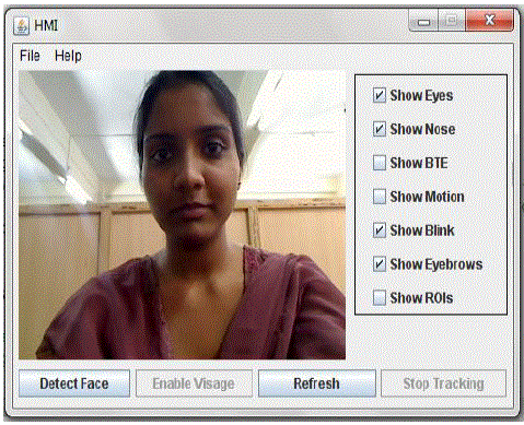
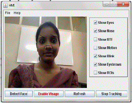
| Fig. 13 is the main GUI of the application. After the wait frame this frame is displayed only if the required webcam is
connected and detected. If the application when run does not find the desired webcam an error message will be
displayed. This frame consists of a video capturing space where the user‟s video is being captured. It consists of four
buttons for four different functions: |
| Detect Face-This button will capture the users video and the screen will now be overlayed with the detected
face features like eyes, nose. These features are marked by black rectangles which are visible to the user. The
features will be detected every now and then as the user moves. So it is expected that the user does not make
rapid movements while and after the face detection as shown in fig. 14. |
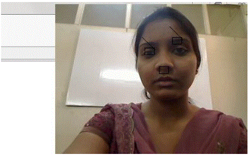
| Enable Visage-This button will provide the user with a small preview window at the upper right corner of the
computer screen so as to check if the features are being correctly tracked. |
| Refresh-This button will refresh the whole feature detection process for the user whenever required. |
| Stop Tracking-This button will stop tracking the features and the black rectangles marked on the video will
disappear |
| The frame also consists of various check boxes that are show eyes, nose, BTE, ROI, blink, motion and eyebrows. This
enables the user to select which feature he/she wants the application to show on the screen. For example if show eyes
and show nose are selected the video will display only the eyes and nose marked by rectangles. |
| This GUI shows the main frame after the detect button is pressed. As the user has selected show eyes, show nose and
show eyebrows from the check box list those respective features are marked accurately. |
| This GUI shows the preview window when enable visage button is pressed as shown in fig. 15. |
RESULTS AND DISCUSSION |
A. Application case study –I |
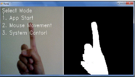
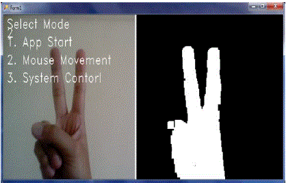
| Following fig. 16 shows the human gesture on the left side and the segmented hand on the right side. This gesture is
used for selection of first mode i.e. Application Start Mode. After selecting the first mode, various applications can be
opened according to the human gesture. |
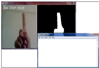
| After Selection of Application Start Mode, user can select any of the gesture and start the appropriate application. In
the fig. 17, gesture with only one finger is used to open the notepad. Two fingers are used to open the Microsoft Word.
Like this, there are 4 options provided to start various applications |
| Following fig. 18 shows the selection of second mode i.e. Mouse Movement Mode. In this mode, user can utilize the
mouse functionalities such as Double Click, Right Click and Cursor Movement. |
B. Application case study –II : |
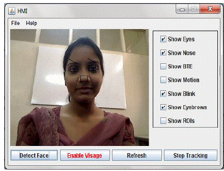
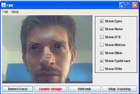
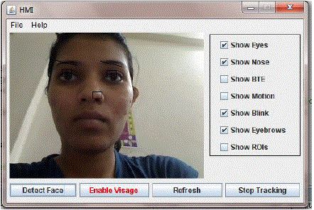
| The GUI designed has been tested with different faces and lightning conditions and obtained a reasonable accuracy in
detecting the face. Once the face has been detected it is used to replace the mouse/ keyboard and cursor controlling is
achieved through the face. Following figure shows the system tested for different persons and lighting conditions as
shown in fig. 19 for Face A under Bright illumination condition, in fig. 20 for face B with beared and face C with low
illumination condition as in fig. 21. |
CONCLUSION |
| We have studied the gesture detection system and a technique is proposed to increase the adaptability of the system.
Two application scenarios are discussed with reference to cursor controlling the computer system with alternative
options to traditional mouse. One application case is using hand gestures and another one by Hands free i.e. face
gestures. The algorithms used are well tested on those system with its application to control the system and obtained a
reasonable accuracy. Hands free computer interface being an important aspect in gesture recognition has wide
applications as discussed earlier. For recognition of the features that is eyes and nose tip several methods are used but
the technique of template matching and using SSR filters and SVM has provided us with effective accuracy using
simple mathematical calculations and logic. With constraints of keeping light conditions constant and a uniform light
colored background, the minimum required accuracy is obtained |
ACKNOWLEDGMENT |
| Authors like to thank UG students who have help in this research work. |
Figures at a glance |
 |
 |
 |
 |
 |
| Figure 1 |
Figure 2 |
Figure 3 |
Figure 4 |
Figure 5 |
| |
 |
 |
 |
 |
 |
| Figure 6 |
Figure 7 |
Figure 8 |
Figure 9 |
Figure 10 |
| |
 |
 |
 |
 |
 |
| Figure 11 |
Figure 12 |
Figure 13 |
Figure 14 |
Figure 15 |
| |
 |
 |
 |
 |
 |
| Figure 16 |
Figure 17 |
Figure 18 |
Figure 19 |
Figure 20 |
| |
 |
| Figure 21 |
|
| |
References |
- PankajBahekar, Nikhil Darekar, Tushar Thakur and ShamlaMantri,âÃâ¬Ã 3D Gesture Recognition for Human-Computer InteractionâÃâ¬ÃÂ, CIITInternational Journal of Artificial Intelligent Systems and Machine Learning, January 2012
- Hojoon Park. âÃâ¬ÃÅA Method for Controlling Mouse Movement using a Real-Time CameraâÃâ¬ÃÂ, Master?s thesis 2010.PragatiGarg, Naveen Aggarwal and SanjeevSofat, âÃâ¬ÃÅVision Based Hand Gesture RecognitionâÃâ¬ÃÂ, World Academy of Science, Engineering andTechnology,2009, pp.1-6.
- Robertson P., Laddaga R., Van Kleek M, âÃâ¬ÃÂVirtual mouse vision based interfaceâÃâ¬ÃÂ, Proceedings of the 9th international conference on Intelligentuser interfaces Pp 177-183, 2004
- Chu-Feng Lien, âÃâ¬ÃÅPortable Vision-Based HCI - A Real-time Hand Mouse System on Handheld DevicesâÃâ¬ÃÂ
- Gary Bradski, Adrian Kaehler, Learning OpenCV, O?Reilly Media, 2008.
- Nilesh J Uke, R.C. Thool, âÃâ¬ÃÅCultivating Research in Computer Vision within Graduates and Post-Graduates using Open SourceâÃâ¬ÃÂ, InternationalJournal of Applied Information Systems (IJAIS), Volume 1âÃâ¬ÃâNo.4, February 2011
- Erik Hjelm and Boon Kee Low, âÃâ¬ÃÅFace detection: A surveyâÃâ¬ÃÂ. Computer Vision and Image Understanding 83, 236âÃâ¬Ãâ274 (2001).
- OrayaSawettanusorn, Yasutaka Senda, ShinjiroKawato, NobujiTetsutani, and Hironori Yamauchi, âÃâ¬ÃÅDetection of Face Representative UsingNewly Proposed FilterâÃâ¬ÃÂ.
- Paul Viola, Michael J.Jones, âÃâ¬ÃÅRobust Real-Time Face DetectionâÃâ¬ÃÂ. International Journal of Computer Vision 57(2), 2004, pp 137âÃâ¬Ãâ154.
- Peter Tino âÃâ¬ÃÅSupport Vector MachinesâÃâ¬ÃÂ. School of Computer Science University of Birmingham 2003.
- ShinjiroKawato and NobujiTetsutani, âÃâ¬ÃÅScale Adaptive Face Detection and Tracking in Real Time with SSR filter and Support Vector MachineâÃâ¬ÃÂ.
- Shashank Gupta, DhavalDholakiya and SunitaBarve., âÃâ¬ÃÅReal-Time Feature based Face Detection and Tracking I-CursorâÃâ¬ÃÂ, In InternationalJournal of Computer Applications 48(24), Published by Foundation of Computer Science, New York, June 2012, pp 1-5.
|