ISSN ONLINE(2278-8875) PRINT (2320-3765)
ISSN ONLINE(2278-8875) PRINT (2320-3765)
Ravindra Sangu1, Veera Reddy.V.C2, Sivanagaraju.S3
|
| Related article at Pubmed, Scholar Google |
Visit for more related articles at International Journal of Advanced Research in Electrical, Electronics and Instrumentation Engineering
The main aim of this paper is damping power system oscillations, which has been accepted as one of the major concerns in power system operation. In the recent past Power System Stabilizer (PSS) was used to damp Low frequency Oscillations. At present FACTs devices, such as static synchronous series compensator (SSSC) is welldesigned to enhance the transient stability of the power system and to damp LFO. In this research a modified Heffron- Phillips model of a single machine infinite bus (SMIB) system installed with SSSC is used. In order to evaluate the performance of the proposed hybrid Fuzzy damping controller in damping LFO, the SMIB power system is subjected to a disturbance such as changes in mechanical power. The complete digital simulations are performed in the MATLAB/Simulink environment to provide comprehensive understanding of the issue. Simulation results demonstrate that the developed Hybrid Fuzzy damping Controller would be more effective in damping electromechanical oscillations in comparison with the conventional fuzzy logic controller and conventional proportional-integral (PI) controller
Keywords |
||||||||
| Low Frequency Oscillations (LFO), static synchronous Series Controller (SSSC), Single Machine-Infinite Bus (SMIB) power system, Hybrid Fuzzy damping controller, Fuzzy logic controller (FLC), PI controller. | ||||||||
INTRODUCTION |
||||||||
| A large power system has many interconnections and bulk power transmissions over long distance. Due to this there low frequency inter area oscillations which make system vulnerable to cascading failures. Many different methods have been proposed to alleviate the oscillations in the power system. For many years, power system stabilizer (PSS) has been one of the traditionally devices used to damp out the oscillations [3]. It is reported that during some operating conditions, PSS may not mitigate the oscillations effectively; hence, other effective alternatives are required in addition to PSSs [4]. | ||||||||
| On the other hand, the advent of flexible ac transmission system (FACTS) devices has led to a new and more versatile approach to control the power system in a desired way [1]. FACTS controllers provide a set of interesting capabilities such as power flow control, reactive power compensation, voltage regulation, damping of oscillations, and so forth [5]-[12]. The static synchronous series compensator (SSSC) is one of the series FACTS devices based on a solid-state voltage source inverter which generates a controllable ac voltage in quadrature with the line current [13]. By this way, the SSSC emulates as an inductive or capacitive reactance and hence controls the power flow in the transmission lines. | ||||||||
| In the literature, different methods have been proposed to design a damping controller for SSSC. For example, in [14] authors have used the phase compensation method to develop a supplementary damping controller for SSSC. The main problem associated with these methods is that the control process is based on the linearized machine model. The other frequently used approach is the proportional-integral (PI) controller. Although the PI controllers offer simplicity and ease of design, their performance deteriorates when the system conditions vary widely or large disturbances occur [14]-[15]. In this context, some new stabilizing control solutions for power system have been presented. Recently, fuzzy logic controllers (FLCs) have emerged as an efficient tool to circumvent these drawbacks. | ||||||||
| This paper addresses the design of a hybrid fuzzy damping controller to attenuate power oscillations by SSSC. The investigation is carried out for a single machine infinite bus (SMIB) power system installed with a SSSC. In the sequel, the linearized Heffron-Phillips model [16] of the examined plant is evolved. A hybrid fuzzy damping controller is utilized to modulate the amplitude modulation index during the transients to enhance the stability of the power system. Subsequently, aiming to provide a fruitful investigation, a comparative study is developed where the hybrid fuzzy damping controller is compared with a conventional fuzzy logic controller and conventional PI controller. | ||||||||
| Simulation results using MATLAB/Simulink exhibits the superior damping of LFO obtained with hybrid fuzzy damping controller than conventional fuzzy logic controller and conventional PI controller. | ||||||||
MODELING OF SINGLE MECHINE INFINITE BUS POWER SYSTEM |
||||||||
| Fig. 1 shows a single machine infinite bus (SMIB) power system installed with a SSSC. In this figure, Xts is the transformer reactance and XLine corresponds to the reactance of the transmission line. Also, Vt and Vb represent the generator terminal voltage and infinite bus voltage respectively. For the SSSC, XSCT is the transformer leakage reactance; VINV is the series injected voltage; CDC is the DC link capacitor; VDC is the voltage at DC link; m is amplitude modulation index and ψ is the phase angle of the series injected voltage. | ||||||||
A. Nonlinear Dynamic Model of the Power System with SSSC |
||||||||
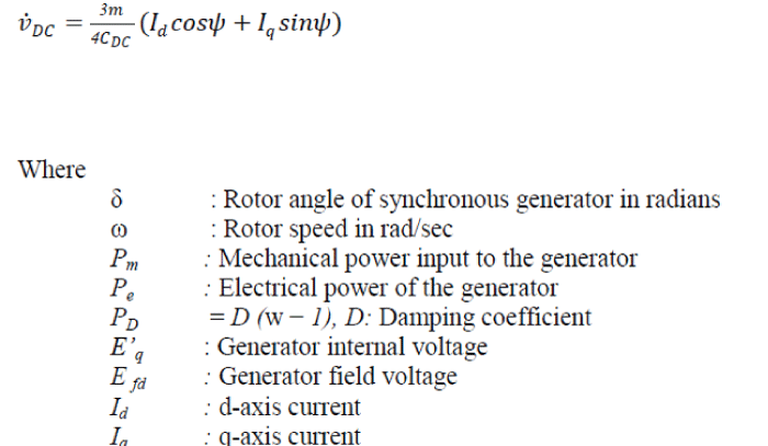
| As the first step, a nonlinear dynamic model for the examined system is derived by neglecting the resistance of all the components including generator, transformer, transmission line, and series converter transformer. The equations specifying the dynamic performance of the SSSC can be written as follows [17]. | ||||||||
 |
||||||||
| Where k is the fixed ratio between the converter AC and DC voltages and is dependent on the inverter structure. For a simple three-phase voltage source converter k is equal with 3/4 [1]. Most of the times, SSSC performs as a pure capacitor or inductor; hence, the only main controllable parameter for SSSC is the amplitude modulation index m .For the work at hand, the IEEE Type-ST1A excitation system is considered. Fig. 2 displays the block diagram of the excitation system where the terminal voltage V and the reference voltage Vref are the input signals. KA and TA are the gain and time constant of the excitation system respectively. | ||||||||
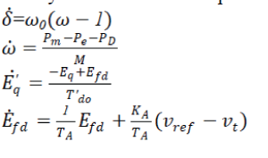
| The dynamic model of the power system in Fig. 1 would be as follows [18]. | ||||||||
 |
||||||||
 |
||||||||
B. Linear Dynamic Model of the Power System with SSSC |
||||||||
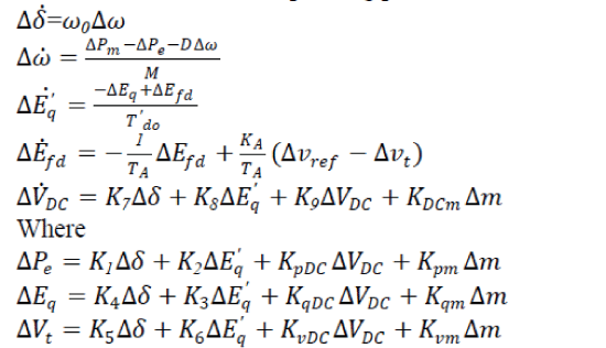
| The linear Heffron-Philips model of an SMIB system including SSSC can be extracted by linearizing the nonlinear model around a nominal operating point [17]. | ||||||||
 |
||||||||
| Fig. 3 exhibits the transfer function model for the modified Heffron-Phillips model of the SMIB system with SSSC. | ||||||||
C. State Space Representation of Linear Model |
||||||||
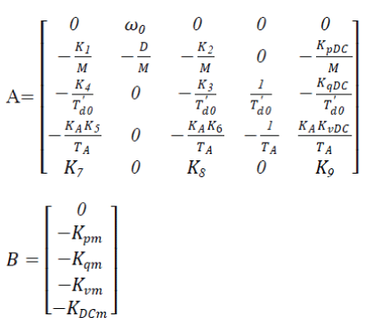
| The modified Heffron-Phillips model can be represented in state-space as: | ||||||||
 |
||||||||
| With respect to (7)-(15), the corresponding system matrix namely A, and the control matrix namely B, are obtained for the investigated power system. | ||||||||
 |
||||||||
D. Calculation of the Heffron-Phillips Model Constants |
||||||||
| The nominal operating point for the power system is set to the given values. | ||||||||
| Pe = 0.8 pu, Qe = 0.144 pu, Vb = 1pu | ||||||||
| The Heffron-Phillips model constants are calculated based on the given values for the nominal operating point. | ||||||||
DEVELOPMENT OF THE CONTROL STRATEGY |
||||||||
A. Introduction of fuzzy logic controller |
||||||||
| In the research work considered in this paper, hybrid fuzzy damping controller is used to coordinate between the various parameters of SMIB based SSSC. In the investigated system, the SSSC series converter amplitude modulation index namely m, provides a control signal to yield better damping of oscillations. | ||||||||
| In general these fuzzy controllers have got a lot of advantages compared to the classical (P, PI, PID), such as the simplicity of control, low cost, high reliability, compactness of the hardware (since fuzzy logic controller just makes use of fuzzy rules) and the possibility to design without knowing the exact mathematical model of the process .Fuzzy logic is one of the successful applications of fuzzy set in which the variables are linguistic rather than the numeric variables & emerged as a consequence of the 1965 proposal of fuzzy set theory by Lotfi Zadeh[19]. Linguistic variables, defined as variables whose values are sentences in a natural language (such as large or small), may be represented by the fuzzy sets. Fuzzy set is an extension of a „crispâÃâ¬ÃŸ set where an element can only belong to a set (ful l membership) or not belong at all (no membership). Fuzzy sets allow partial membership, which means that an element may partially belong to more than one set. A fuzzy set A of a universe of discourse | ||||||||
| A fuzzy logic controller is based on a set of control rules called as the fuzzy rules among the linguistic variables [20]. These rules are expressed in the form of conditional statements. Our basic structure of the fuzzy logic coordination controller to damp out the oscillations in the power system consists of 3 important parts, viz., fuzzification, knowledge base - decision making logic (inference system) and the de-fuzzification [21]. | ||||||||
| FLC generates the required small change for amplitude modulation index to control the magnitude of the injected voltage [22]. The centroid defuzzyfication technique was used in this fuzzy controller. Fig. 4 demonstrates the FLC structure. In this case, a two–input, one–output FLC is considered. The input signals are angular speed deviation (Δw) and load angle deviation (Δδ) and the resultant output signal is the amplitude modulation index (Δm) for SSSC converter. | ||||||||
B. Hybrid fuzzy damping controller |
||||||||
| It is a combination of conventional fuzzy logic controller (FLC) and conventional PI controller. The internal structure of the hybrid fuzzy damping controller is shown in the Fig. 5. The necessary inputs to the decision-making unit blocks are the rule-based units and the data based block units. The fuzzification unit converts the crisp data into linguistic variables. The decision making unit decides in the linguistic variables with the help of logical linguistic rules supplied by the rule base unit and the relevant data supplied by the data base. | ||||||||
| The output of the decision-making unit is given as input to the de-fuzzification unit and the linguistic variables of the signal are converted back into the numeric form of data in the crisp form [5]. The decision-making unit uses the conditional rules of „IF-THEN-ELSEâÃâ¬ÃŸ, which can be observed from the algorithm mentioned below. | ||||||||
| The membership functions of the input and output signals are shown in Fig. 6. There are two linguistic variable for each input variable, including, “Positive” (P), and “Negative” (N). On the other hand, for the output variable there are three linguistic variables, namely, “Positive” (P), “Zero” (Z), and “Negative” (N). | ||||||||
| The developed fuzzy rules included in the fuzzy coordinated controller are given below in the form of an algorithm as follows: | ||||||||
| If Δw is P and Δδ is P, then Δm is P. | ||||||||
| If Δw is P and Δδ is N, then Δm is Z. | ||||||||
| If Δw is N and Δδ is P, then Δm is Z. | ||||||||
| If Δw is N and Δδ is N, then Δm is N. | ||||||||
| Fig.7 demonstrates the output of fuzzy controller versus its inputs. As it can be seen in fig.7, the rules surface is smooth which a desirable option in design procedure. | ||||||||
SIMULATION RESULTS AND DISCUSSION |
||||||||
| In order to compare the proposed hybrid fuzzy damping controller performance with the conventional fuzzy logic controller and conventional PI controller some useful simulations are provided. The contingency simulated is a step change in mechanical power (ΔPm = 0.01) which occurs at t=5sec and lasts for 0.1 sec. | ||||||||
| At the beginning, the SSSC has no damping controller. For this case, the angular speed deviation and also the load angle deviation responses with time are displayed in Fig.8 and 9. These figures reveal that when there is no damping controller, the LFO damping is very poor. Hence an auxiliary damping controller is essentially required to improve the transient stability of the system. | ||||||||
| In the second case, simulations are performed with the same contingency in mechanical power but the SSSC has been equipped with a damping controller. Simulation results are shown in Fig.10 and 11. With respect to these figures, the hybrid fuzzy damping controller exhibits better damping than the conventional fuzzy logic controller and conventional PI controller. Likewise, the power system transient stability is increased when the SSSC is equipped with the hybrid fuzzy damping controller. Simulation results validate the efficiency of the proposed hybrid fuzzy logic damping controller and its better performance is emphasized. | ||||||||
CONCLUSION |
||||||||
| This paper has demonstrated the hybrid fuzzy damping controller in a single machine infinite bus power system to damp low frequency oscillations. A comparative study between the hybrid fuzzy damping controller, conventional fuzzy logic controller and conventional PI controller shows that the proposed hybrid fuzzy damping controller has superior performance and influence in transient stability enhancement and oscillations damping. Simulation results validate the efficiency of the proposed hybrid fuzzy damping controller and its better performance is emphasized. Consequently, the hybrid fuzzy damping controller would be a better option in the design of damping controllers. | ||||||||
Figures at a glance |
||||||||
|
||||||||
|
||||||||
|
||||||||
References |
||||||||
|