ISSN ONLINE(2319-8753)PRINT(2347-6710)
ISSN ONLINE(2319-8753)PRINT(2347-6710)
| V.V.Rajasegharan, Dr.L.Premalatha, B.Vishnupriya Department of Electrical and Electronics Engineering, Anand Institute of Higher Technology, Chennai, India |
| Related article at Pubmed, Scholar Google |
Visit for more related articles at International Journal of Innovative Research in Science, Engineering and Technology
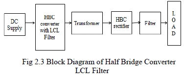
For the growing energy distribution challenges, active distribution networks are found to be an ideal choice. With the rapid development of semiconductor and power electronic techniques, the dc distribution system is ready as an alternative scheme to the existing ac distribution systems due to its high power quality and reliability performance. Half Bridge Converter (HBC) or Full Bridge Converter were the commonly used topologies. Among them, Half bridge converter has significant role in power electronics and drives application. The converter can be proposed in different ways according to the area of application. A modification is made with the existing HBC by the addition of LCL filter at input side to reduce the inrush current, voltage stress on switches and di/dt losses. The main advantage of employing the proposed converter is to reduce the input current ripple without adding a large input filter. Hence the above mentioned HBC with LCL filter is the proposed topology which can shape the input current waveform to a non pulsating fashion.
Keywords |
| Half Bridge Converter, LCL Filter, Battery charger, Current ripple reduction |
INTRODUCTION |
| The recent advancement of power device technology mainly by the growth of MOSFETs has made possible to improve performance of power electronic devices. MOSFET are popularly used due to its higher frequency, high impedance, low voltage stress and mainly consume less Dc power. Dc-Dc converters are widely used in industrial applications such as dc motor drives, office appliances and communication equipments [1].Dc-Dc converters are always essential to convert the dc bus voltage to different voltage levels for the load devices. Dc-Dc converters have high efficiency, high power density, high voltage gain and reduced ripple voltage. The common types of Dc-Dc converters are divided into two types on how they transfer the energy. The energy can go from the input to the magnetic through load or the energy can be stored in the magnetic to be released later to the load [2,3]. In this paper among the Dc-Dc converters Half Bridge Converter (HBC) is widely used to have low voltage stress, low EMI and high efficiency performance. LCL Filter is added with the HBC to reduce the input current ripple. The experimental circuit investigated in this paper is Dc-Dc HBC converter, which allows the conversion of energy from higher level to lower level [4,5]. HBC with LCL filter is used to reduce the inrush current, decrease the switching losses and to achieve high frequency operation. |
| The size of LCL filter is reduced which is a main advantage. This is extensively used in many other different industrial applications such as battery charging applications, office applications and in telecommunication devices. The analysis was carried out on the Matlab – Simulink and the results confirm the reduction of input current ripple and reduced voltage spikes. |
PROPOSED SYSTEM |
| A. Half Bridge Converter |
| Half Bridge Converter (HBC) is an attractive topology and used for middle power applications due to its simplicity. The half bridge converter is another form of an isolated forward converter. When the voltage on the power transistor in the single ended forward converter because too high, the half bridge converter is used to reduce the voltage stress. One of the main features of half bridge converter is it reduces the off stage voltage stress. Thus the cost and voltage stress is reduced. |
| The half bridge converter acts as a forward converter but it uses a bridge circuit which consists of two transistors to drive the transformer. The half bridge converter can be used as two back- back converter. The output of HBC is double to that of forward converter supplying the same input voltage. The half bridge converter originates from the step down converter. The equal valued capacitors C1 & C2 are inserted across the DC voltage in series forming the half VDC to primary winding of the transformer. The Dc voltage VDC/2 or – VDC/2 is applied. The MOSFET switches S1 and S2 conduct on the same duty cycle. |
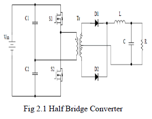 |
| The two switches connect the transformer across the capacitors alternatively. Full Bridge Converter requires extra capacitor to eliminate the Dc bias in the transformer. But in the proposed Half Bridge Converter extra capacitor is not needed because the two transistors itself automatically correct the difference of the switching by changing their voltage. |
| Half Bridge Converter originates from the buck converter. The MOSFET voltage stress is half of the input voltage in HBC because the two capacitors share the input voltage evenly. |
| B. LCL Filter |
| The LCL filter is mostly used with a transformer in half bridge converter or full bridge converter. The LCL filter has been promising approach to reduce harmonic current, and to reduce the inrush current. |
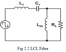 |
| The Dc characteristics of LCL filter can be determined by two resonant frequencies. One is low resonant frequency and another is high resonant frequency. Lr and Cr determine the higher resonant frequency and Lm and Lr determine the lower resonant frequency. The frequency is expressed as |
| f0 = 1/ 2π√Lr Cr |
| Q = √Lr Cr |
| Ln = Lm / Lr |
| Where, fo – frequency |
| Q – Quality factor |
| Ln – ratio between magnetizing and resonant Inductors Lm and Lr |
| Both these operating conditions reduce the input current ripple. The features of LCL filter are improved efficiency, smaller switching loss, narrow frequency variation range over wide range and less stress on rectifiers. |
| C. Half Bridge Converter with LCL Filter |
| The proposed system is half bridge converter with LCL filter. A capacitor is inserted between two primary windings of the transformer. It is used to reduce the input current ripple, and to achieve low voltage stress, lossless snubbing and voltage clamping features. The proposed converter reduces the Electromagnetic Interference problem also. |
 |
| A number of bridge type converters have been proposed. The size of the input filter can be reduced without adding a large input filter. The cost also reduced. |
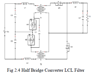 |
| During turn off interval a non - zero input current is maintained and during turn on interval the input current is shared. The voltage spike across the switch is eliminated by absorbing the leakage inductance. |
COMPARISON OF CONVENTIONAL AND PROPOSED CONVERTER |
| In the conventional system much effort has been focused on minimizing the voltage stress on switches, reducing switching losses and to achieve high frequency operation. In spite of that it has high dv/dt noise and high electromagnetic interference. It needs a large input filter to mitigate the noise problems which results in increasing the cost and reducing the system performance. |
| In the proposed half bridge converter with LCL filter the input current ripple is reduced by inserting a capacitor in between the primary windings of the transformer. Because of this it does not require a large input filter so the cost is reduced. Voltage spike across the switch is eliminated by absorbing the leakage inductance energy. The undesired harmonics can be reduced and the proposed half bridge converter shape the input current waveform to a non pulsating fashion. |
DESIGN CONSIDERATIONS |
| Instantaneous Output Voltage |
 |
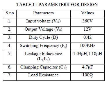 |
SIMULATION RESULTS |
| The simulation was carried out in MATLAB/ SIMULINK tool to verify theoretical. The switching frequency is set to 100 Khz. SIMULINK is a graphical extension to MATLAB for modeling and simulation of systems. The switching circuit of the conventional and proposed system are provided as follows. |
CONVENTIONAL SYSTEM: |
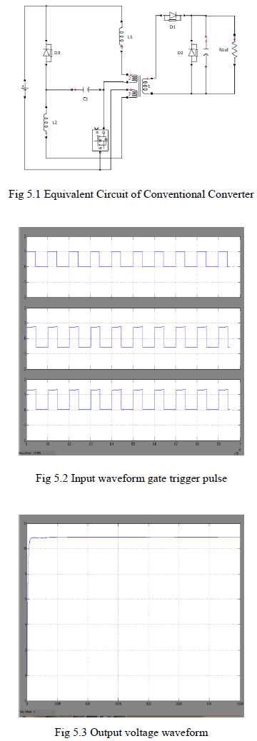 |
PROPOSED SYSTEM |
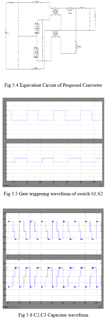 |
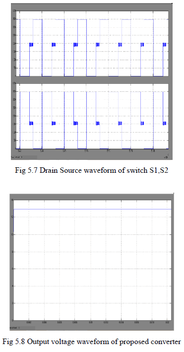 |
CONCLUSION |
| In this paper the input current ripple is reduced using Half Bridge Converter with LCL filter. The leakage inductance energy is absorbed resulting in eliminating voltage spikes. Voltage clamping functions and built in snubbing also performed. The voltage stress and switching losses are reduced. The ripple and undesired harmonics can be reduced without adding a large input filter. Because of these features the proposed converter is suitable for Dc- Dc converters, office applications, telecommunication devices and for battery charging applications. |
References |
|