Keywords
|
| Piconet, Sactternet, Personal Area Network (PAN), Adhoc Network, Delay time, Energy consumption. |
INTRODUCTION
|
| Recently, much attention has been given to the research and development of Personal Area Networks (PAN). These networks are comprised of personal devices, such as cellular phones, PDAs and laptops, in close proximity to each other. Bluetooth is an emerging PAN technology which enables portable devices to connect and communicate wirelessly via short-range ad-hoc networks [1], [2] since its announcement in late spring 1998; the Bluetooth technology has attracted a vast amount of research. However, the issue of capacity assignment in Bluetooth networks has been rarely investigated. Moreover, most of the research regarding network protocols has been done via simulation [3]. In this paper we formulate a model for the short range transaction system and delay analysis and energy consumption concerns of the transaction system. |
| Bluetooth; a promising wireless personal area network technology to provide a low power, low cost, globally uniform radio interface between any two devices with Bluetooth support. Today, Bluetooth is on the verge of being ubiquitously deployed over a wide range of devices. |
| An ad hoc network based on Bluetooth, however, brings new challenges. There are specific Bluetooth constraints not present in other wireless networks. For example, a Bluetooth network is composed of piconets. Each piconet contains one master and up to seven slaves. Piconets can be connected into a larger scatternet (Figure 1) by sharing slaves. As shown by Miklos et al. [9] and Zurbes [10], the configuration of a scatternet has significant impact on the performance of the network. For instance, when a scatternet contains more piconets, the rate of packet collisions increases. Before we can make effective use of Bluetooth ad hoc networking, we must first devise an efficient model to form a scatternet from isolated Bluetooth devices. [8] |
| In this paper, we analyze the delay time analysis and energy consumption issues for our proposed short range wireless transaction system. |
| Study the problem of scatternet formation in the situation where the devices are not in-range of one another. The communication range is at least 10 meters according to the current Bluetooth specification. This means that our formation model should work when the maximum distance between any two devices is more than 10 meters. |
| We adopt a layer approach to this problem. First, we investigate how these devices can be organized into scatternets. We design and evaluate the performance of a new scatternet formation model. Second, as a subroutine of the formation model, we study how the devices can discover each other efficiently and generate optimal path between to nodes. [11, 12] |
| This paper is organized as follows: In Section 2, we discuss the background of our research in order to get a better understanding of how our model formulated. In section 3 we discuss our proximity wireless transaction system. In Section 4, we introduce with dynamic optimal path selection. Delay time analysis using eclipse emulator in Section 5. We present analyses and simulation results of our model using NS2 in Section 6. In Section 7 we mentioned the concluding remarks for our research work. |
| Scatternets increase Bluetooth’s usability multi-folds and open many new arenas to provide excellent value-added services to the users. Numerous applications may be built over them to unleash the potential of Bluetooth. The main ingredients of a scatternet-based application include a topology formation, model design and a routing algorithm, which themselves are of many types as the Bluetooth specification does not define any specific ones. Every implementation of these applications requires an implementation of one of these algorithms hence making one re-invent the wheel most of the time. This calls for a standard model framework to integrate all the applications and algorithms in a seamless, modular and reusable fashion. |
| To build a highly flexible and robust model to deploy a wide variety of scatternet-based applications over Bluetooth, we have identified the following requirements: |
| A. Platform Independent |
| Any application that wishes to be deployed over Bluetooth should aim to be portable over a wide range of platforms. This platform independence is required on two accounts: |
1. Stack Independence:
|
| With the coming of Bluetooth, came a surplus of stacks, both open-source and proprietary. A basic Bluetooth stack spans at least four layers of the OSI network model from the physical to the transport. Most of these layers are directly accessible to the applications running at the top. With each stack having its own API and specifications, porting an application over each of these stacks poses an extraordinary task. So the idea is to provide a standard API between the applications and the stacks such that an application complying with this standard API becomes independent of the underlying implementation. |
2. Device Independence:
|
| Bluetooth intends to get deployed on just any wireless device that may ever exist. To achieve device independence, the application should be written in a programming language that is portable across most of these devices. Java comes as a natural choice. Java 2 Platform Micro Edition (J2ME), with its Connected Limited Device Configuration (CLDC) augmented with the Mobile Information Device Profile (MIDP), is the most widely deployed version of Java and spans almost every wireless device that possesses the capability to connect to a network. |
| So to meet both the above requirements of stack independence and device independence, we need a standard API between the applications and the stack and that too Java-based. |
3. Plug-n-Play
|
| Scatternet formation and routing algorithms are responsible for defining the characteristics of a scatternet. A scatternet can deliver better performance to particular type of applications if these algorithms are application-oriented. By simply switching among algorithms the users can easily decide what works best for them. So to allow selection of algorithms at run-time, we have integrated them into the architecture in a plug-n-play fashion. In this way, the user may also download and run algorithm modules that may be developed independently but in accordance with the architecture. |
| Based on above; we have design a new data transaction system for short range communication and proposed a solution to find optimal path in this proposed model. The work for the same is published [14, 15]. |
PROXIMITY WIRELESS TRANSACTION SYSTEM DESIGN
|
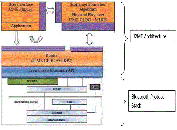
| We have developed a proximity wireless transaction system which can help extend the range of Bluetooth communication and provide a free infrastructure for communication using eclipse and J2ME. The architecture is shown in figure -2. [11, 12] |
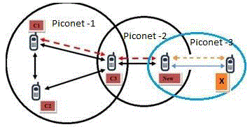
| In this particular transaction model a device C1 (piconet-1) could send a message to device New (piconet-2), which is not within the range of C1 (piconet-1), via devices C3, which are within short range of each other. Same way X (piconet-3) is in range New; which is not range of C1 even though transaction system. |
| In figure -3, C1, C2 and C3 are in one piconet, means they are directly as well as indirectly connected with each other. While node New is in second piconet, which is directly connected with C3. Node X is in third piconet. Which is directly connected with node New. |
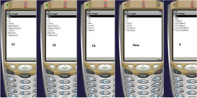
| The figure- 4 for shows how nodes are arranged in eclipse emulator as mentioned in figure -3. [14] |
DYNAMIC OPTIMAL PATH SELECTION
|
| In this new design, we have evaluated extension possibilities derived for more than two hopes in network and exploring different routing path / link for communication. |
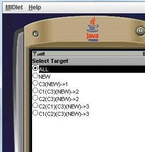
| After successful implementation of above architecture design in figure - 4; our next task to work on routing mechanism for shortest path in the above network design as shown in figure 5. [13] |
| In order to display dynamic optimal path in our model we have use * sign against the path. When two paths are same with equal hop we consider the path which found first in the network as an optimal path. The same is shown in figure 6. [7] |
DELAY TIME ANALYSIS
|
| To find end to end delay, cumulative delay; we have first emulated the model in eclipse. |
| A. End2End delays: |
| End2End delay = time (in seconds) when packet was received by OTHER NODE - time (in seconds) when packet was sent by CURRENT NODE. In our short range wireless network the calculations of packets sent at source trace level and received at destination trace level are considered. Trace level at the source and destination nodes can be chosen from the list. [4] |
| When data is transmitted from source (C1) to destination (X) at that time it passes from different intermediate nodes. That delay is due to packet receiving and packet forwarding time. The same is shown in below figure. The delay at node NEW. |
| B. Cumulative Delay: |
| Average number of nodes receiving packets = sum of numbers of all the intermediate nodes (nodes between source and destination nodes) receiving packets sent by all the source nodes / number of received packets at all the destination nodes. [6] |
| Average number of nodes forwarding packets = sum of numbers of all the intermediate nodes (nodes between source and destination nodes) forwarding packets sent by all the source nodes / number of received packets at all the destination nodes. |
| The total or cumulative delay i.e. the delay between sender and receiver is shown in following figure. Cumulative delay is nothing but the total time taken by packets at each intermediate node. Below figure shows the total delay time at node X. |
| C. Traffic Delay: |
| We have emulated the by populating nodes in our network model. As a result we state that when numbers of intermediate nodes are more the delay time is more and less the number of node resultant in to less delay. In addition to that we have also emulated data transmission between two nodes when they are directly and indirectly connected with each other. From the result we can state that directly connected nodes takes less time and indirectly connected nodes more time because of delay at intermediate node. Time for directly and indirectly connected node. [4,5] |
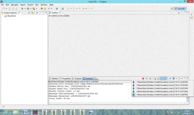
| In our case when C1 and C2 are directly connected it takes 15 ms (figure 9). When we transmit data from C1 to C3 via C2 it takes more delay time. In our case it takes 46 ms (figure 10). |
SIMULATION USING NS2
|
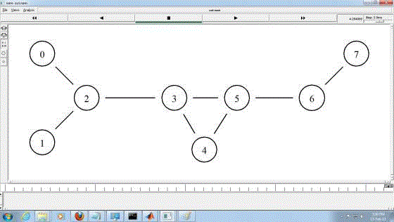
| In order to evaluate packet generation and packet size along with the delay time analysis and energy consumption we simulated the same transaction system using NS2. In NS2 first we have setup the topology as shown in figure 11. |
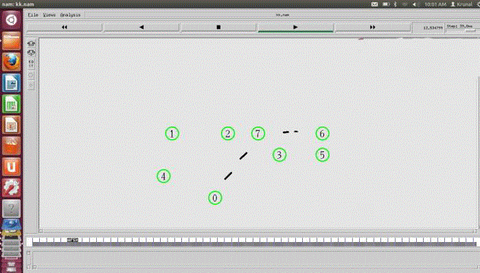
| Figure 12 provides network information of our model. Node 0, 1,4 in first piconet, node 2,3,7 in second piconet and node 3,5,6 in third piconet. Node 7 is the intermediate node through which node 0 and node 6 can able to communicate with eachohter. |
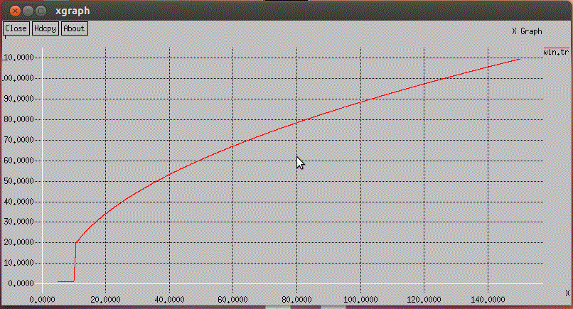
| We have also examined the energy consumption by nodes in our model using NS2. Initial energy we have assume 1000 Joule for each node as shown in figure 13 and the result at the end of simulation that we have shown in figure 14 in our case energy is 991.864574 Joule and the graph for the same is generated using the xgraph as shown in figure 15. |
| During the analysis we found that during scatternet formation, there are many devices trying to get connected at the same time, so the inquiry and page processes will occur. We call this propagation for device discovery when a set of in range devices try to connect with each other. In the following, we discuss our approach and present the simulation results using xgraph. |
| Graph indicates that in the beginning for propagation or device discovery and connection establishment it requires more energy and afterwards it indicates the energy consumed by the nodes. |
CONCLUSION
|
| This work provides the facility of multiple path analysis and dynamic optimal path analysis. It gives almost real behaviour of path transmission with the mobility of the nodes. By using this work, once all possible paths from the source and the destination are found, the link stability of the nodes are observed, and basis of these parameters, the paths are shown with numbers, these numbers shows the number of intermediate hops between source and destination. Less the number between source and destination is more optimal path. |
| In addition, we presented end-to-end delay, cumulative delay and traffic delay analysis using eclipse and energy consumption issues by NS2 simulator. |
Figures at a glance
|
 |
 |
 |
 |
 |
| Figure 1 |
Figure 2 |
Figure 3 |
Figure 4 |
Figure 5 |
|
 |
 |
 |
 |
 |
| Figure 6 |
Figure 7 |
Figure 8 |
Figure 9 |
Figure 10 |
|
 |
 |
 |
 |
 |
| Figure 11 |
Figure 12 |
Figure 13 |
Figure 14 |
Figure 15 |
|
References
|
- http://en.wikipedia.org/wiki/Bluetooth
- http://www.bluetooth.com/Pages/Bluetooth-Home.aspx
- Gil, Z. and Adrian, S., “Capacity Assignment in Bluetooth Scatternets – Analysis and Algorithms”, CCIT Report pp. 355., 2001.
- Gwo-Jong, Y. and Wei-Chen, H., “A Minimum Delay Routing Protocol for Bluetooth Radio Networks”, Tamsui Oxford Journal of Mathematical Sciences, Aletheia University 20(2) pp. 291-314, 2004.
- Chang, W., Y., Kun-Ming, Y., Shu, L. L., “Reducing Inter-piconet Delay for Large-Scale Bluetooth Scatternets”, Emerging Technologies in Knowledge Discovery and Data Mining Lecture Notes in Computer Science Volume 4819, pp 562-573, 2007.
- Misic, V.B., “Minimizing end-to-end delays in Bluetooth scatternet with a slave/slave bridge”, Proceedings of Eleventh International Conference on Computer Communications and Networks, pp 634 – 639, 2002.
- Rehman, M.U. and Husbullah, H.B., “Optimal path selection in Bluetooth scatternet based on fuzzy set theory”, IEEE potentials, pp 930- 935, 2010.
- Chih-Min, Y. and Jing-Rung, Y., “A configurable routing protocol for Bluetooth wireless network”, American Journal of Engineering and Technology Research, pp 43-46, Vol. 11 No. 12, 2011.
- Miklos, G,, Racz, A., Turanyi, Z., Valko, A., and Johansson, P., “Performance aspects of Bluetooth scatternet formation”, In Proceedings of The First Annual Workshop on Mobile Ad Hoc Networking and Computing, 2000.
- Zurbes , S., “Considerations on link and system throughput of Bluetooth networks”, In Proceedings of the 11th IEEE International Symposium on Personal, Indoor and Mobile Radio Communications, volume 2, pp. 1315–1319, 2000.
- Kamani, K.C., Kathiriya, D.R. and Virpariya P.V., “Proposed Bluetooth Protocol for Short Range Communication” International Journal of Information and Computing Technology, 2011.
- Kamani, K.C., Kathiriya, D.R., Virpariya P.V., and Ghodasara ,Y.R., “A Routing Mechanism in Bluetooth: A Short Range Communication Technology” Proceddings of National Conference on Technology Driven Society, 2011.
- Kamani, K.C., Kathiriya, D.R., Virpariya P.V., and Ghodasara ,Y.R., “An Protocol Usage Model and An Architecture Design for Bluetooth – A Short Range Transaction System. International Journal of Advance Research in Computer Science, Vol. 1 No. 4., 2010.
- Kamani, K.C., Kathiriya, D.R. and Virpariya P.V., “Architectural Challenges in Designing of Data Transaction System for Short Range Communication”, International Journal of Management, IT and Engineering (IJMIE), Vol.2 Issue 8, 2012.
- Kamani, K.C., Kathiriya, D.R. and Ghodasara ,Y.R., “Optimal Path Selection in Short Range Wireless Communication”, IEEE Xplore Digital Library, ISBN No: 978-1-4799-0316-0, pp. 246 – 250 available on: http://ieeexplore.ieee.org, 2013.
|