Keywords
|
| ABC, Accelerometer, COMSOL, Double folded beam, MEMS. |
INTRODUCTION
|
| An accelerometer is an electromechanical device that measures acceleration forces. These forces may be static like the gravitational force, or they could be dynamic caused by vibration or movement. On earth all objects fall with acceleration is defined as ‘g’ which is equal to 9.81m/s2. It acts as a mass attached with spring, which experiences the acceleration where the mass gets displaced to the position that the spring is able to accelerate at the same rate as the acceleration in question[1]. Accelerometers are widely used in sensors for screen orientation, hard disk drive protection, activity monitoring for power management, gesture recognition for interactive games and much more. MEMS (Micro Electro Mechanical System) refer to the technology of integrating electrical and mechanical components with the feature size of 1~1000 microns. MEMS accelerometer has been successfully applied for the airbag deployment systems in automobiles [2], which measures negative acceleration of the vehicle. The reason behind the increasing popularity of MEMS technology in accelerometers is that they are smaller, reliable and are produced at the cost of conventional accelerometers. Accelerometers with high sensitivity, high resolution and low power consumption are needed in a number of applications ranging from GPS augmented inertial navigation systems to guidance and stabilization of satellites and space craft’s [1]. |
PROPOSED METHODOLOGY
|
| MEMS accelerometer die area is directly relates to the production cost, and is understandably a very important criterion to the manufacturer to reduce the production cost. Since the cost to produce the wafer of MEMS device is fairly constant, the cost of a single device depends on how many devices can fit on to a single wafer [3]. An optimum design of accelerometer can be found out if it meets the required constraints. Due to the complex nature of the problem Artificial Bee Colony (ABC) algorithm [4] is involved, which minimizes the die area by satisfying all the constraints. This method of optimization provides better performance and reliability than other optimization algorithms which uses these desired parameters [5]. The constraint values of optimized parameters through ABC algorithm is compared with the COMSOL designed structure by applying the required acceleration forces and there by studying the stress and displacement capabilities. |
DOUBLE FOLDED BEAM ACCELEROMETER
|
| MEMS accelerometer under study is a capacitive type with applicable dimensions and axes, these double folded beam assemblies with proof mass make up the equivalent spring system. Double folded beam is selected due to its relatively wide range of linearity when proof mass experiences large displacement [6]. This folded beam suspension can be used to achieve high sensitivity by offering low spring constant in the sensing direction [7]. To measure displacement, capacitive sensors exist on either side of the proof mass whose sensitivity is proportional to the side length of the mass. The displacement values are measured based on the voltage signal obtained from the sensor. On equating Newton’s second law to Hook’s law the acceleration experienced by the mass can be easily determined by kx= ma, where ‘k’ is the spring constant of the beams, ‘m’ is the mass of the accelerometer and ‘a’ is the acceleration in sensing direction. Ideally the legs (beams) of the structure would be made as long as possible for softer springs and mass as large as possible. This would result in a greater displacement and thus the maximized acceleration resolution. When a concentrated load is applied on to the proof mass, the linear spring constant will be, |
 |
| Where ‘f’ is the force and ‘d’ is the displacement in x-direction. It is noted that the rate of change of displacement us inversely proportional to the spring constant provided a given acceleration and fixed mass. Therefore for high sensitivity, a smaller spring constant in the direction of the sensing acceleration is needed [8]. The folded flexure design strongly reduces the axial force and exhibits much larger linear deflection range. |
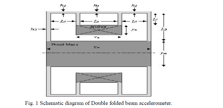
| Fig (1) shows the representative diagram of double folded beam structure with length of beams as L1, L2, L3, and Lm, the length and width of the proof mass as Xm and Ym respectively. The depth or thickness of the accelerometer as a whole is taken as 1.8μm. |
SELECTION OF MATERIAL
|
| Achieving low cost of microelectronic devices and high reliability depends on the material used and their performance to the application. The principle materials used in mechanical structures in common are polysilicon, single crystal silicon, silicon carbide (SiC) etc [9]. Polysilicon materials are used for designing the beam structure based on its reliability analysis [10] [11]. Single crystal silicon (100) having density of 2330kg/m3 and fracture strength of 4000Mpa which is very attractive material for high strength application, is used as proof mass. The melting point of silicon is 14000°c and thermal expansion coefficient which is much less than that of steel makes it dimensionally stable even at high temperatures. Although these materials posses low toughness, its high strength at small scale increase the strain levels and decrease the possibility of material fracture and damage. |
OPTIMIZATION THROUGH ABC ALGORITHM
|
| Artificial Bee Colony (ABC) algorithm given by Karaboga is based on the foraging behaviour of natural honey bee swarms [12]. A colony of bee consists of three groups as Employed bees, Onlooker bees and scout bees. Employed bees are meant for exploiting food source, onlooker bees are those that are waiting in the hive for the employed bees to share the information about the food source it exploited. Onlooker bees choose the best food source based on the probability, proportional to the quality of food source. Scout bees are those that are searching for food source in the neighbourhood of the hive. As employed bee whose food source gets abandoned becomes scout bee. Constrained problems of optimization are carried out through this algorithm, where the fitness of each solution was taken for fulfilling the required constraints. The values of these parameters are selected by probability calculation [13] as in Eqn (2). |
 |
| Fitness represents the quality and quantity of the individual food source and maximum fitness gives the fitness of the whole colony. The parameters of high fitness values are selected in each cycle of algorithm food search process. The fitness values of beam lengths, proof mass width and their respective die area is given through the iteration process [4]. The values obtained through the final iteration process were tabulated in table (1). |
THEORETICAL ANALYSIS
|
| In order to analyse the double folded beam design, two different operating conditions are considered. They include the sensor motion resolution (~0.005g), maximum acceleration survival (2000g) and for each condition the displacement of proof mass and maximum stress is determined. The first test analyse the accelerometer when it experiences a load just large enough to register a signal from the sensor. The second test considers the accelerometer’s reaction to experience a load of 2000g, which is the maximum value for survival [14]. Stress from maximum acceleration was taken in to account to protect the device from accidental shock. The high acceleration used in this criterion is not intended to be operational value, it is instead included to account for accelerations produced by unexceptional treatment caused by dropping the device. The maximum allowable acceleration was optimized in the direction of intended acceleration (xaxis). The folded beams are connected to the anchor material which is also silicon at both sides of the proof mass. The base of anchors is fixed to the substrate layer, proving a constraint to the substrate by placing fixed restraints on their bottom surfaces. The working operation and output of the accelerometer depends on the effective mass of the movable parts or the proof mass (m), stiffness constant of the suspension beam (k),Damping air surrounding the structure, figure overlap area of comb drive, initial capacitance etc.[16] Among this stiffness constant and the mass has significant impact on the response of the accelerometer. The beam width (h1, h2, h3, hm =1.8μm), thickness of the proof mass and beams (b1, b2, b3, bm= 1.8μm) are the defined parameters and (L1, L2, L3, Ym) are the optimized parameters from the algorithm [4]. Proof mass length is calculated by, Xm= Lb+2(L2+h1+h3) μm which is 235.6 μm, while the mass of the accelerometer by neglecting the mass of the springs or beams is found out to be 1.064x10⁻¹² (kg) from M= ρXmYmbm (kg), ‘ρ’ is the density of single crystal silicon. |
| Fig. (2) Shows the COMSOL design of double folded beam structure which is created from the iterations of optimized parameters. |
| The differential equation of the folded beam bending acts as the basis for theoretical analysis of the device. The relevant equation for calculating the spring constant and the moment of beam [13] is given in Eqn (2), |
 |
| From the above Eqn. (2) and (3) the spring constant of the folded beam flexure is calculated as 0.0541N/m and the moment of the beam due to acceleration force is 1.2794x10⁻¹⁰. By using the above values stress and displacements are calculated for the 2 conditions mentioned above. |
DESIGN ANALYSIS
|
| COMSOL multiphysics is a finite element analysis simulation software package for engineering and physics applications especially for multiphysics or coupled phenomenon. To perform stress and strain analysis structural mechanics module is preferred with full multiphysics capabilities [15], as it comprises large deformation, shell, and beam and contact capabilities. The geometry of accelerometer is created or designed with silicon material for proof mass and anchors, polysilicon for beams. This design defines the gravitational force in x-direction by eliminating all degrees if freedom. The mesh is created for the entire geometry with maximum element size as 86.8μm. |
A. Motion resolution
|
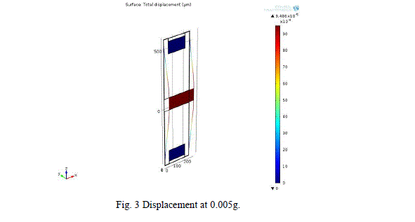
| In this case, the proof mass undergoes an acceleration of 0.005g that is the force of 5.127x10⁻¹² N for a mass of 1.0464x10⁻¹⁰ kg, which roughly generates a displacement equal to the sensor’s motion resolution. Figure 3, gives the design computed through COMSOL which computes to a maximum displacement of 9.486x10⁻⁵μm. |
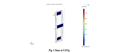
| Figure 4, shows the maximum stress of 339.56 N/m2 experienced by the device, especially beams. |
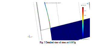
| A more detailed view of stress of beam near the proof mass joint as shown in Fig. 5, |
B. Maximum survival of acceleration
|
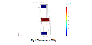
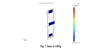
| One of the design goals is to ensure that the material of the device will not fail for acceleration force greater than 2000g, this is the maximum acceleration force above which the material failure occurs. Structural design is processed for maximum acceleration survival that is a force of 2.05x10⁻⁶N, which creates maximum stress of 1.357x10⁸N/m2, especially on the edge of the beams and in the joints with the proof mass and displaces to about 37.9μm. Figure 6 and figure 7 shows the displacement and stress in the beams, |
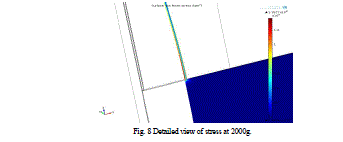
| Detailed view of stress at the joints of beam and anchor is given in fig.7 |
RESULTS AND DISCUSSION
|
| The simulated design values of stress and displacement for 2 types of forces are compared with theoretical values obtained through MATLAB. Table II gives the minimum survival analysis and Table III gives the maximum acceleration survival. |
| From the tables as described, the MATLAB values agree well with the design values, which help in satisfying the engineering goals and constraints. |
CONCLUSION
|
| Design and simulation of double folded beam accelerometer is created in COMSOL Multiphysics. The design values are verified through theoretical values which satisfy all the constraints for a minimum die area of 111437.39μm2. |
Tables at a glance
|
|
|
| |
Figures at a glance
|
 |
 |
 |
 |
| Figure 1 |
Figure 2 |
Figure 3 |
Figure 4 |
|
 |
 |
 |
 |
| Figure 5 |
Figure 6 |
Figure 7 |
Figure 8 |
|
| |
References
|
- N. Yazdi, F. Ayazi and K. Najafi, "Micromachined Inertial Sensors", Proceedings of the IEEE, vol. 86, no. 8, pp. 1640-1659,1998.
- V. Josselin, P. Touboul and R. Kielbasa, Sensors and Actuators A: Physical, vol.78, no. (2-3), pp.92–98, 1999.
- Chan Kyu Choi, Yong Il Kim and Hong Hee Yoo, “Manufacturing yield and cost estimation of a MEMS accelerometer based on statistical uncertainty analysis”, Journal of Mechanical Science and Technology vol. 28 , no. 2, pp. 429~435, 2014.
- Krushnasamy V.S, Vimala Juliet.A, “Design parameter optimization on Artificial Bee colony (ABC) algorithm for MEMS accelerometer,” journal of theoretical and applied information technology, vol. 60, no. 2, pp.274-283, Feb 2014.
- Krushnasamy V.S, Vimala Juliet.A, “MEMS accelerometer design optimization using Genetic Algorithm”, Advanced material research, vol. 705, pp.288-294, 2013.
- Abdulaziz N. Radwan and Ridha S. Almikhlafi “Performance comparison of commonly used MEMS springs: Double folded, U-shaped, and Fish hook,” IEEE SIECPC, pp. 1-6, Apr. 2013.
- Prashant Singh, Pooja Srivastava, Rajshri kumari chaudary, and prachi gupta, “Effect of Different proof mass supports on Accelerometer sensitivity”, IEEE ICEETS, pp. 896-900, Apr. 2013.
- Badariah Bais, Burhanuddin Yeop Majlis, “Suspension Design Analysis on the Performance of MEMS Area-changed Lateral Capacitive Accelerometer”, IEEE ICSE, pp. 335-339, 2004.
- S.M.Spearing, “Material issues in microelectromechanical systems (MEMS),” Acta materialia, vol. 48, pp. 79-196, 2000
- Xingguo Xiong, Yu-Liang Wu and Wen-Ben Jone, “Material Fatigue and Reliability of MEMS Accelerometers” , IEEE International Symposium on Defect and Fault Tolerance of VLSI Systems, pp. 314-322 Oct.2008
- D.Effa, P. Nieva, Z. Andrew, S. Lancaster, “Design and Modeling of a MEMS Accelerometer for a Novel Virtual Button User Interface,” IEEE TICSTH, pp. 597-602, sept. 2009.
- Dervis Karaboga , Bahriye Akay “A comparative study of Artificial Bee Colony algorithm”, Applied Mathematics and Computation, vol. 214, pp. 108– 132, 2009.
- Ivona Ivona Brajevic, Milan Tuba, “An upgraded artificial bee colony (ABC) algorithm for constrained optimization problems”, Journal of Intelligent Manuf, vol. 24, issue 4, pp.729–740, 2013.
- Liwei lin, “Parametric design of MEMS accelerometer”, ME-128, Apr. 2006.
- http://en.wikipedia.org/wiki/COMSOL_Multiphysics.
- W.Wai-chi, A.A.Azid, B.Y.Majlis, “Formulation of stiffness constant and effective mass for a folded beam,” Archives of Mechanics, vol. 62, no. 5, pp. 405-418, 2010.
|

