Keywords
|
| Antenna, Directional characteristics, Linear Arrays, Fractal Arrays, Cantor set, Multiband. |
INTRODUCTION
|
| Antenna arrays [1] design is necessary with very high directive characteristics to meet the demand of long distance communications. Wireless communication services and a related application is driving the attention to the design of multi frequency and small antennas.. Fractal shaped antennas have already been proved to have some unique characteristics that are linked to the geometrical properties of fractal. As it was thoroughly discussed in [10]-[13], the self similarity property of fractals makes them specially suitable to design multi frequency antennas. In this paper we present and discussed of fractal linear arrays and its characteristics are comparing the conventional arrays. |
| Fractal object have some unique geometrical properties one of them is the possible to enclose in a finite area and infinitely long curve. The Koch monopole is numerically and experimentally analyzed by the researchers, number of iterations are Koch monopole are increased, the Q of the antenna approaches fundamental limit for small antennas [14]. |
| The tele comoperators and equipment manufacturers can produce variety of communications systems, like cellular communications, global positioning, satellite communications, and others, each one of this systems operates at several frequency bands. |
| To give service to the users, each system needs to have an antenna that has to work in the frequency band employed for the specific system. The tendency during last year’s had been to use one antenna for each system, but this solution is in efficient in terms of space usage, and it is very expensive. The variety of communication systems suggests that there is a need for multiband antennas. The use of fractal geometry is new solution to the design of multiband antennas and arrays. |
| Fractal geometries have found an intricate place in science as a representation of some of the unique geometrical features occurring in nature. Fractal was first defined by Benoit Mandelbrot [2] in 1975 as a way of classifying structures whose dimensions were not whole numbers. These geometries have been used previously to characterized unique occurrences in nature that were difficult to define with Euclidean geometries, including the length of coastlines, the density of clouds, and branching of trees [3]. |
FORMULATION
|
A. CONVENTIONAL LINEAR ARRAY ANTENNA:
|
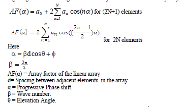
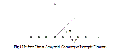
| A linear array consists of N number of isotropic elements, uniformly spaced at a distance d apart along with the Z-axis as shown in the Fig.1 [4]. Linear array is usually consists of identical elements position in a regular geometrical arrangement. The array factor of the linear array may be expressed in the form [1, 5] |
 |
B. FRACTALLINEAR ARRAY ANTENNA:
|
| Radiation Fractals of fractal linear arrays have recently been developed [6]-[8] by fast recursive algorithms. These algorithms are based on the fact that fractal arrays can be formed recursively through the repetitive application of a generating array. Generating subarray is a small array at scale one ( X= 1 ) used to construct larger arrays at higher scales (i.e., X> 1 ). In many cases, the generating subarray has elements that are turned on and off in a certain pattern. A set formula for copying, scaling, and translation of the generating subarray is then followed in order to produce the fractal array. The array factor for a fractal array of this type may be expressed in the general form |
 |
| Where GA(α) represents the array factor associated with the generating subarray. The parameter δ is a scale or expansion factor that governs how large the array grows with each recursive application of the generating subarray and X is the level of Iteration. |
| This array becomes fractal like when appropriate elements are turned OFF or removed, therefore |
| an= 1 if element n is turned ON |
| = 0 if element n is turned OFF |
| The simplest scheme for constructing a fractal linear array follows the recipe for the cantor set [9]. Cantor arrays also have own multiband properties. |
| So it has multi frequencies (Fn) and derived by using equation (5) |
 |
| Here F0 is the design frequency |
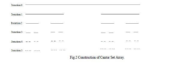
| The basic Cantor array shown in figure-2 created by starting with a three-element generating sub array, and then applying it repeatedly over Xscales of growth. The generating sub array in this case has three uniformly spaced elements, with the center element turned off or removed, i.e., 101. The Cantor array is generated [4] recursively by replacing 1 by 101 and 0 by 000 at each stage of the construction. For example, at the second stage of construction (X = 2), the array pattern would look like |
| 1 0 1 0 0 0 1 0 1 |
| at the third stage ( X = 3 ), we would have |
| 1 0 1 0 0 0 1 0 1 0 0 0 0 0 0 0 0 0 1 0 1 0 0 0 1 0 1 |
| at the fourth stage ( X = 4 ), we would have |
| 101 0 101 0 0 0 101 0 , 101 0 0 0 0 0 0 0 0 0 101 0 101 0 0 0 101 0 101 |
| at the Fifth stage ( X = 5 ), we would have |
| 1010101 0 1010101 0 0 0 1010101 0 1010101 0 0 0 0 0 0 0 0 0 1010101 0 1010101 0 0 0 1010101 0 1010101 |
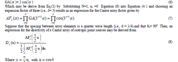
| The first five iterations are presented in the following Table.1. The array factor of the three-element generating sub array with the representation 101 is |
 |
RESULTS
|
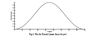
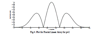
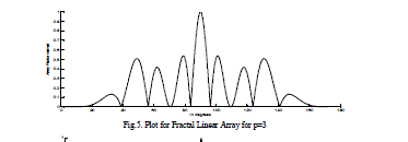
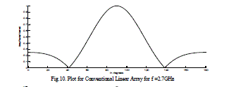
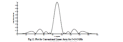
| The radiation field patterns for conventional array and Fractal array are designed and simulated by using MATLAB. The Arrays are designed with the design frequency F0 =24.3GHz with the each element spacing λ/4. The level five of Cantor linear array 101 have number of active elements of 32 and total number of elements 243. This array operates at 5 frequencies depending on the equation (5). Depending on the frequency the radiation field patterns of the fractal linear array and conventional linear arrays are designed and simulated and presented from figures 3-12. The directivity, HPBW and SLL’s are calculated and presented in tables 2-3. It evident from the results at low frequencies the conventional linear array shows as a point source and cannot be operate at multiband frequencies, whereas Fractal linear array operates at multi band frequencies. |
| In the above tables 2,3 Directivity, HPBW, SLL for Fractal Linear and for Conventional Linear Array are considered individually and compared with each other. For conventional linear array at 24.3 Ghz, Directivity is of 12.6dB for the same fractal linear array getting Directivity 15.05 so total improvement in the directivity by 3dB. So Fractal Linear Array gives better results when compared with Conventional Linear Array. |
| Above figures gives relation between array factor to the elevation angle Ãâ°Ãµ for different stages of the Fractal Linear Array, as the total number of stages increases, the field patterns of fractal linear array antenna have high side lobe level, lower half power beam width, and high directivity when comparing with the conventional linear array. |
CONCLUSION
|
| The field pattern for conventional linear and fractal linear array antennas are designed and simulated at a frequency2.43GHz. It is evident from results of the conventional array antenna has sidelobes and narrow beam width at the designed frequency but at lower frequency it behaves as a point source. The fractal linear array antenna has operates at all frequencies, and it is not acts as a point source at other than designed and lower frequencies. Therefore the fractal linear antenna is suitable for operating at multiband. From the results it observed that the field patterns of fractal linear array antenna have high sidelobe level, lower half power beam width, and high directivity when comparing with the conventional linear array. |
Tables at a glance
|
|
|
| |
Figures at a glance
|
 |
 |
 |
 |
| Figure 1 |
Figure 2 |
Figure 3 |
Figure 4 |
|
 |
 |
 |
 |
| Figure 5 |
Figure 6 |
Figure 7 |
Figure 8 |
|
 |
 |
 |
 |
| Figure 9 |
Figure 10 |
Figure 11 |
Figure 12 |
|
| |
References
|
- Balanis, C. A., Antenna Theory: Analysis and Design, 2nd edition, Wiley, 1997.
- Mandelbrot, B. B., The Fractal Geometry of Nature, W. H. Free-man and Company, New York, 1983.
- Gianvittorio, J., “Fractal antennas: Design, characterization and application,” Master’s Thesis, University of California, Los Angeles, 2000.
- Werner, D. H., R. L. Haupt, and P. L. Werner, “Fractal Antenna engineering: The theory and design of fractal antenna arrays,” IEEE Antennas and Propagation Magazine, Vol. 41, No. 5, 37–59,October 1999.
- Stutzman, W. L. and G. A. Thiele, Antenna Theory and Design, 2nd edition, John Wiley & Sons, New York, 1998.
- Baliarda, C. P. and R. Pous, “Fractal design of multi-band and low side-lobe arrays,” IEEE Transactions on Antennas andPropagation, Vol. 44, No. 5, 730–739, May 1996.
- Werner, D. H. and R. L. Haupt, “Fractal construction of linear and planar arrays,” Proceedings IEEE Antennas Propagation Soc.Int. Symp., Vol. 3, 1968–1971, July 1997.
- Werner, D. H. and R. Mittra, Frontiers in Electromagnetics, IEEE Press, 2000.
- Peitgen, H. O., H. Jurgens, and D. Saupe, “Chaos and Fractals:New Frontiers of Science”, Springer-Verlag, Inc., New York, 1992.
- C.Puente, R.Pous, J.Romeu, and S.Garcia, “Antennas fractals o multi fractales” Spanish patent no.2112163, May 19, 1995.
- C.Puente, J.Romeu, R.Pous, X. Garecia, and F.Benitez, “Fractal multiband antenna based on the dierpinski gasket.” Electron, Lett., vol.32, no.1, pp. 1-2, Jan 1996.
- C.Puente, “Fractal antennas,” Ph.D. dissertation, dept. signal theory and commun, universitatPolitecnica de catalunya, June1997.
- C.Puente, J.Romeu, R.Pous, and A.Cardama, “On the dehavior of the sierpinski multiband antenna,” IEEE Trans. Antennas Propagat., Vol.46, pp.517-524, Apr.1998.
- Carles Puente Baliarda, JordiRomeu, and Angel Cardama, “ The Koch Monopole: A Small Fractal Antenna”, IEEE Transactions On Antenna and propagation, Vol.48, No.11, November 2000.
|


