Keywords
|
| Fractal Antenna, Koch Curve, Sierpinski Gasket, Multiband Antenna |
INTRODUCTION
|
| Today’s wireless communication, satellite communication and advanced military systems, require antennas of higher performance, higher gain, wider bandwidth, multiband support, low cost and conventionally smaller design dimensions. To fulfil all these requirements researchers are looking for more advanced antenna designs. One such field of advanced antenna design is Fractal Antennas. The concept of fractal antenna came from fractals existing in nature [1][4]. Fractal antennas are designed using fractal geometries which show properties like self-similarity, space filling, and complexity in their structure. B.B.Mandelbrot described a family of complex shapes that possess an inherent self-similarity or selfaffinity in their geometrical structure [1]. The original idea behind the development of fractal geometry came largely from an in-depth study of the patterns existing in nature. Patterns existing in nature, show self-similarity and space filling properties. These properties of fractal designs are utilized in fractal antenna designing for achieving wideband/multiband behaviour. The fractal theory approach has been used as a size compression technique for all types of antennas such as dipoles, loops, patches and so on leading to the development of fractal antenna. Fractal geometry allows combining antennas of different frequencies avoiding interference, allowing us to design tri-band and tetra-band antennas with a very small size and the same gain factor as a traditional antenna. |
| In this paper fractal antenna is designed using triangular Koch curve and Sierpinski gasket fractal geometries. In this work two designs of fractal antennas have been studied. The designs are simulated using 4NEC2 software. The simulation results show that the Triangular KOCH Curve Design when given iteration two times it shows multiband behaviour whereas the Serpinski gaskets design not. Also the Koch Fractal technique that has been applied to the antenna structure reduces the length of the elements making it suitable for small wireless devices. |
ANTENNA CONCEPTS
|
| The IEEE definition for an antenna as given by Stutz man and Thiele [8] states that it is that part of transmitting and receiving antenna that is designed to transmit and receive electromagnetic waves. The process of conveying information or intelligence or message from one place to another is known as communication. When electromagnetic waves or radio waves are utilized for the communication purpose, then it is called as radio communication [9]. |
| The essential requirements of any communication system are: |
| Means of transmitting the message or intelligence. |
| Means to carry the message from one place to another, and |
| Means to receive the message. |
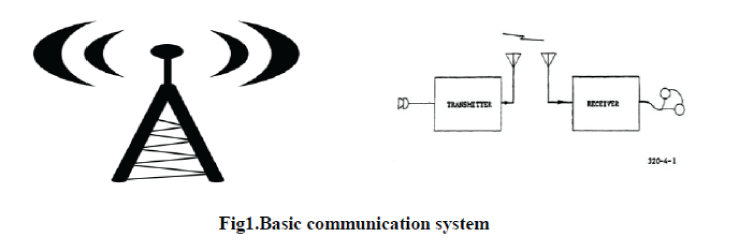
| In other words, as shown in Fig 1, |
| Transmitter, |
| Medium and |
| Receiver. |
A. Antenna Parameters
|
| The performance of an antenna is described in terms of following parameters. These parameters specify physical and electrical characteristics of an antenna [3] [9]. |
| Resonant frequency: The "resonant frequency" and "electrical resonance" is related to the electrical length of an antenna. The electrical length is usually the physical length of the wire divided by its velocity factor (the ratio of the speed of wave propagation in the wire to the speed of light in a vacuum). Typically an antenna is tuned for a specific frequency, and is effective for a range of frequencies that are usually centered on that resonant frequency. |
| Gain: Gain as a parameter gives the measure of how much power is transmitted in the direction of maximum radiation to that of an isotropic source. |
| Directivity: The maximum directive gain is called as the directivity of an antenna and is denoted by D. it is the ratio of Maximum radiation intensity to its average radiation intensity. |
| Radiation Pattern: The radiation pattern of an antenna is the geometric pattern of the relative field strengths of the field emitted by the antenna. |
| Voltage Standing Wave Ratio (VSWR): The voltage standing wave ratio (VSWR) is defined as the ratio of the maximum voltage to the minimum voltage in a standing wave pattern. |
| Bandwidth: The bandwidth of an antenna is the range of frequencies over which it is effective, usually centered on the resonant frequency. |
| Reflection Coefficient: A reflection coefficient defines the amplitude or the intensity of a reflected wave relative to an incident wave. |
B. Applications
|
| Antennas are used in systems such as: |
| Radio and television broadcasting, |
| point-to-point radio communication, |
| Wireless LAN |
| Radar and space exploration. |
| In air or outer space |
| Under water or even through soil and rock at certain frequencies for short distances. |
FRACTAL ANTENNA
|
| Fractal antennas are still in their early stages of development. In 1988, the first fractal antenna later on patent and published was built by Dr Nathan Cohen. As we know antenna size and operating wavelength are related such that, when the size of an antenna is made much smaller than the operating wavelength or less than one fourth of the operating wavelength (λ/4), it becomes highly inefficient. Currently, many portable communications systems use a simple monopole with a matching circuit. However, if the monopole were very short compared to the wavelength, the radiation resistance decreases, the stored reactive energy increases, and the radiation efficiency would decrease. As a result, the matching circuitry can become quite complicated. And when matched, they result in high value of quality factor ’Q’, i.e. a very narrow bandwidth. So a new approach to antenna design was called for. There are a variety of approaches that have been developed over the years, which can be utilized to achieve one or more of these design objectives. Recently, the possibility of designing antenna that can utilize the properties of fractals to achieve these goals, at least in part, has attracted a lot of attention. |
| These antennas as mentioned in [1] are nature inspired antennas. The fractal designs existing in nature show self similar and space filling behaviour. These two properties of fractals are used in fractal antenna designing. There are different fractal antennas geometry types defined. These geometries are natural extension of Euclidean geometry. A fractal design is obtained by applying a finite number of times an iterative process [7][10].There are several fractal geometries existing in nature. The properties of these geometries are incorporated in the designing of antenna. |
A.Properties of Fractal Geometries
|
| Space Filling Properties: Space filling property is based on space filling curves. |
| Self Similarity: A self similar object is exactly or approximately similar to a part of itself. |
B. Fractal Geometric Types
|
| Fractal geometry involves a recursive generating methodology that results in contours with infinitely intricate fine structures. These geometries are modern discovery even though fractals in nature have been around forever. These are based on shapes being self similar. These are usually based on a building process that gets repeated and repeated. |
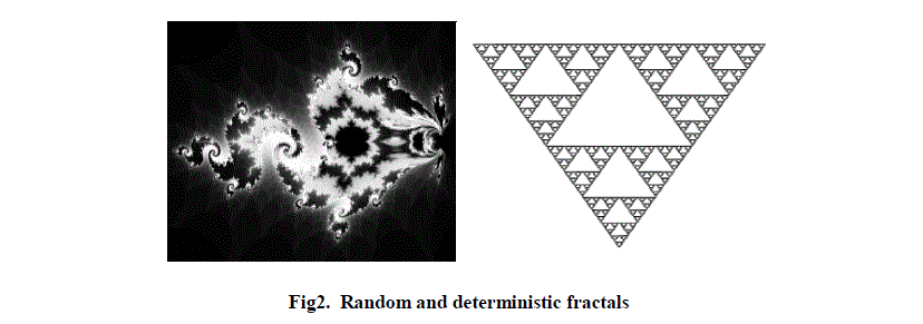
| There are two geometric types (as shown in Fig 2) for fractal defined: |
| Random: Random fractals are quite familiar and many look like random walks (Brownian motion); dendrites; or lightning bolts. |
| Deterministic (chaotic): They take a 'motif' or 'generator' and apply it on successive size scales. |
| In this paper two fractal antenna geometries are discussed. These are: |
A.TRIANGULAR KOCH CURVE GEOMETRY
|
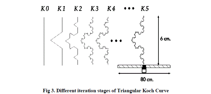
| These antennas are designed on the basis of Koch curves. In 1998 the von Koch monopole became the first reported fractal small antenna that improved the features of some classical antennas in terms of bandwidth, resonance frequency, and radiation resistance [4][10]. The Koch curve is the limiting curve obtained by applying this construction an infinite number of times. The von Koch fractal grows by a factor of 4 to 3, giving a fractal similarity dimension of about 1.26 (log 4 / log 3). |
| A Triangular Koch curve as shown in Fig 3 is generated by replacing the middle third section of straight wire with a bent section of wire of triangular shape that covers the original middle third section. The resulting structure then grows in length by 4/3[5] [10]. |
C. SIERPINSKI GASKET GEOMETRY
|
| The Sierpinski gasket design is named after the polish mathematician Sierpinski. He described the properties of this fractal design in 1916 [6]. The design is obtained by subtracting the central part of the main triangle with an inverted triangle. After the subtraction, three equal triangles remain on the structure, each one being half of the size of the original one. Iterating the same subtraction procedure on the remaining triangles infinite number of times, the ideal fractal Sierpinski gasket is obtained. The Fig 4 shows the different iteration stages of Sierpinski gasket design. |
Advantages
|
| Small in size |
| Better input impedance |
| Wideband/multiband support(one antenna can be used instead of many ) |
| Consistence performance over huge frequency range. |
| Added inductance and capacitance without components. |
Disadvantages
|
| Fabrication and design is little complicated. |
| Lower gain in some cases. |
| Numerical limitations. |
| Performance starts to decrease after first little iteration. |
Applications
|
| In Building Communication: Fractal antenna provides universal wideband antenna technology that is ideal for in – building communication applications. Operating over 150MHz to 6GHz, fractal antennas deliver excellent Omni directional coverage in a compact form factor. |
| Wireless Networks: Fractal Antenna Systems provide excellent advanced antenna technology that enables emerging wireless protocols, such as ZigBee, WiMAX and MIMO, to deliver their maximum potential. |
| Universal Tactic Communication: Future communications systems will use cognitive radios that require vast bandwidths, with one antenna. |
| Mobile Devices: From PDAs to cellular phones to mobile computing, today’s wireless devices require compact, high performance multiband antennas. At the same time, packaging constraints demand that each component, especially the antenna, be inherently versatile. |
| Telematics: Today’s automobile can have dozens of antennas that provide everything from emergency notification and navigational services to satellites radio and TV. Multiple antennas create performance and form factor challenges, as well as aesthetic design issues. |
| RFID (Radio frequency identification): Fractal antenna system provides a compact, low cost solution for multitude of RFID applications. Because fractal antennas are small and versatile, they are ideal for more compact RFID equipment. |
RESULTS AND DISCUSSION
|
A. Koch Curve fractal geometry:
|
| The fractal dipole antenna is designed using triangular Koch Curve fractal geometry. The antenna is designed in XZ plane with design frequency equal to 400MHz and 800MHz. The designed fractal geometry is shown in Fig 5. |
| The antenna designed at operating frequency 400MHz resonates at two frequencies thus showing multiband behaviour after 2nd iteration. |
| The antenna designed at operating frequency 800MHz resonates at two frequencies thus showing multiband behaviour after 2nd iteration. |
B. Sierpinski Gasket fractal geometry
|
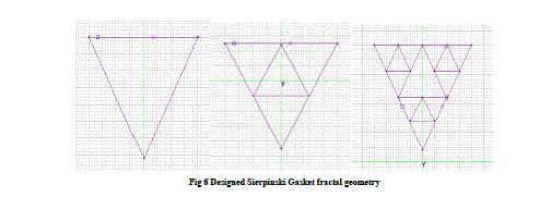
| The fractal antenna is designed using Sierpinski Gasket fractal geometry. The antenna is designed in XZ plane with design frequency equal to 400MHz and 800MHz.The designed fractal geometry is shown in Fig 6. |
| The antenna designed at operating frequency 400MHz doesn’t show multiband behaviour after 2nd iteration. |
| The antenna designed at operating frequency 800MHz doesn’t show multiband behaviour after 2nd iteration. |
| The results of 1st module show that the Koch fractal antenna for iteration 2 operates at two resonant frequencies of 600MHz and 2200MHz in first case. And in second case the Koch Fractal Antenna operates at resonant frequencies of 1000MHz and 3000MHz. At these frequencies the designed antennas have VSWR < 2 and Reflection Coefficient < - 10dB (parameters defined for practical antennas [3] [6]). As we can see from the simulation results that first design i.e. Triangular Koch Curve is showing good results in comparison to the second design i.eSierpinski gasket at both the frequencies (i) 400MHz (ii) 800MHz in terms of tested parameters. Also it is observed that the Triangular Koch curve geometry is showing multiband behaviour. The results are shown in tabular form below. |
CONCLUSION
|
| The designs are simulated using 4NEC2 software. The simulation results show that the Triangular KOCH Curve Design when given iteration two times it shows multiband behavior whereas the Serpinski gaskets design resonates at single frequency. Also the Koch Fractal technique that has been applied to the antenna structure reduces the length of the elements. In this work, two different fractal designs are investigated for two different frequencies that pertain to 400 MHz and 800 MHz. The results of the work done, show that the designs are suitable for wireless applications (more specifically for GSM and UMTS services) as the devices for these applications require small, multiband antennas. The Triangular Koch Curve antenna geometry shows multiband behavior thus it can be used as multiband antenna while the Sierpinski gasket design, after iteration resonates at single frequency. |
| The designed Triangular Koch Curve antenna is small in size thus can be used in small wireless communication devices. The Koch Fractal technique that has been applied to the antenna structure reduces the length of the elements. |
| The Triangular Koch Curve antenna for iteration 2 operates at two resonant frequencies of 600MHz and 2200MHz in first case. The Triangular Koch Curve antenna for iteration 2 operates at two resonant frequencies of 1000MHz and 3000MHz in second case. These frequencies are suitable for GSM, UMTS and Bluetooth applications [MBa10] [Kal07]. Thus this particular antenna design can be used for fabricating an antenna that can support GSM, UMTS and Bluetooth services. |
| Also it has been seen that in Sierpinski design, the gain parameter is showing a decrease in value. So in future these designs can be modified further to improve the gain parameter values. Since fractal antenna designing is still in its early stages of development a lot of work is still required to improve the performance of the antenna. In this paper fractal antenna is designed for only two iterations using KOCH curve geometry and Sierpinski Gasket geometry. Sierpinski design can be iterated more for obtaining better performance in terms of multiband behaviour. |
ACKNOWLEDGEMENT
|
| My sincere thanks to Dr.SavinaBansal and Dr. R. K. Bansal, co-authors, for their guidance and support. I also want to acknowledge all the researchers whose works have been used as reference in preparing this paper. |
Tables at a glance
|
 |
 |
 |
 |
| Table 1 |
Table 2 |
Table 3 |
Table 4 |
|
| |
Figures at a glance
|
 |
 |
 |
| Figure 1 |
Figure 2 |
Figure 3 |
|
 |
 |
 |
| Figure 4 |
Figure 5 |
Figure 6 |
|
| |
References
|
- Mandelbrot, B.B. (1982). The Fractal Geometry of Nature. W.H. Freeman and Company
- Nathan Cohen (2002) "Fractal antennas and fractal resonators" United states Patent.
- Antenna types and its basics by Er. SajjadHussainKanju 2009.
- Philip Felber “Fractal Antenna, a literature study”.December 12, 2000.
- C. Puente, J. Romeu and A. Cardama, “The Koch monopole: a small fractal antenna”. IEEE Trans. On Antennas and Propagation, Vol. 48, pp. 1173-1781, 2001.
- C. A. Balanis, Antenna Theory: Analysis and Design,NewYork, Wiley, 1997.
- R. L. Yadava, M. Ram and S. Das, “Multiband Triangular Fractal Antenna for Mobile Communications International Journal of Engineering Science and Technology Vol. 2(11), 2010, 6335-6348.
- Stutz man, W.L. and Thiele, G.A., Antenna Theory and Design, John Wiley & Sons, Inc, 1998.
- Fawwaz Jinan Jibrael, “Multiband Cross Dipole AntennaBased on The Triangular and Quadratic Fractal Koch Curve,” International Journal of Engineering (IJE), Vol 4, Issue 3.
- Douglas H. Werner', Randy L. Haup, and Pingjuan L. Werner, “Fractal Antenna Engineering: The Theory and Design of Fractal Antenna Arrays.IEEE Antennas and Propagation Magazine, Vol. 41, ppNo. 5, October I999.
- D. Kalra, “Antenna Miniaturization Using Fractals,” M.Sc. Thesis, University of Deemed, India, 2007.
|