International Journal of Advanced Research in Electrical, Electronics and Instrumentation Engineering
ISSN ONLINE(2278-8875) PRINT (2320-3765)
ISSN ONLINE(2278-8875) PRINT (2320-3765)
I.Vedasangamithra1, N.Selvarani2
|
| Related article at Pubmed, Scholar Google |
Visit for more related articles at International Journal of Advanced Research in Electrical, Electronics and Instrumentation Engineering
This work presents a detailed analysis of the two most well-known maximum power point tracking(MPPT) algorithms: the perturb-and-observe(P&O)and the incremental conductance(INC)for photovoltaic system(PV)in multilevel cascaded H-bridge inverter. The proposed system presents output voltage, and efficiency based comparison of both P&O and INC algorithm. Width of the pulse is varied by varying operating value of the system. In this system produces the nine level sinusoidal output voltage using H-bridge inverter. This set up is analysed by using Matlab simulink and the efficiency of multilevel inverter outputs are compared.
Keywords |
| Photovoltaic cell (PV); Perturb-and-observe(P&O); Incremental conductance(INC);Boost converter; modelling; design; maximum power point tracking(MPPT);simulation, H-bridge multilevel inverter(HBMLI). |
INTRODUCTION |
| The rapid increase in the demand for electricity and the recent change in the environmental conditions such as global warming led to a need for new source of energy that is cheaper and sustainable with less carbon emissions. Solar energy has offered promising results in the quest of finding the solution to the problem. The harnessing of solar energy using PV modules comes with its own problems that arise from the change in insulation conditions[1-2]. These changes in insulation conditions severely affect the efficiency and output power of the PV modules. A great deal of research has been done to improve the efficiency of the PV modules. A number of methods to track the maximum power point of a PV module have been proposed to solve the problem of efficiency and products using these methods have been manufactured and are now commercially available for consumers[1]. This research then looks at how a different type of converter affects the output power of the module and also investigates if the MPPT that are said to be highly efficient and do track the true maximum power point under the various conditions[1-3]. |
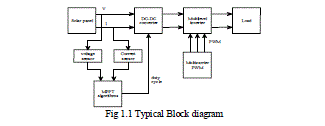
| A MPPT is used for extracting the maximum power from the solar PV module and transferring that power to the load. A dc/dc converter acts as an interface between the load and the module[5]. By changing the duty cycle the load impedance as seen by the source is varied and matched at the point of the peak power with the source so as to transfer the maximum power[4]. Therefore MPPT techniques are needed to maintain the PV array operating at its MPP. Many MPPT techniques have been proposed in the literature; Example are the Perturb and Observe (P&O) methods, Incremental Conductance (IC) methods etc. In this work two most popular of MPPT techniques Perturb and Observe (P&O) and Incremental Conductance methods are implemented on cascaded multilevel inverter and then the output voltage, and efficiency is compared, This work has been done in the simulation. |
 |
DESIGN OF PHOTOVOLTAIC SYSTEM |
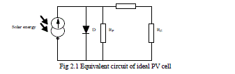
| Photovoltaic (PV) cell is a semiconductor device that absorbs and converts the energy of light into electricity by photovoltaic effect[3]. Fig 2.1 shows the equivalent circuit of Photovoltaic cell. |
 |
DC/DC CONVERTER |
| A DC/DC converters are used to transferring maximum power from the solar PV cell to the load. This converter provide an interface between the load and the PV cell. By changing the duty cycle, the load impedance is varied and matched at the point of the peak power with the source, so as to transfer the maximum power. |
Operating Principle of Boost Converter |
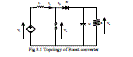
| Fig 3.1 shows the topology of Boost converter. For this converter, power flow is controlled by means of the on/off duty cycle of the switching transistor. When the switch is On means, the current flows through the inductor in clockwise, and inductor stores the Vi I1 energy. When the switch is Off means, the current will be reduced for increasing impedance. The inductor release the current through diode D to the capacitor C and load R. The polarity of inductor will change. And the energy accumulated in the inductor during the On-State will be released, (Vc-Vi)I1 toff. where D is the duty cycle. It represents the fraction of the commutation period T during which the switch is On. Since , the output voltage is always higher than the source voltage. |
 |
MPPT TECHNIQUES |
| On the P-V curve, there is a point where the PV cell generates the maximum power, this point always locates at the knee of the curve, and is called maximum power point (MPP). Since the output power of PV cell is fully based on the solar radiation, temperature and load, the output characteristic is nonlinear. It is necessary for the PV system to work at the maximum power point under changing external environment to achieve best performance. Extracting the maximum power from the PV cell and transferring that power to the load can be done by MPPT algorithm. Several algorithms are used to track maximum power point. The most used are, |
| i. Perturb and Observe algorithm (P&O) |
| ii. Incremental Conductance algorithm (Inc Cond) |
i. Perturb and Observe algorithm (P&O) |
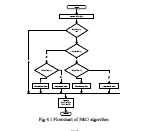
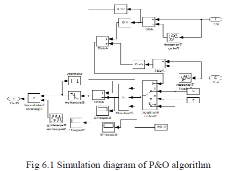
| For simplicity and ease of implementation the P&O algorithm is mostly used. As its name implies, this method works by disrupting the system and observing the impact on power output of PV module. If the operating voltage is disturbed in a given direction and that the power increases (dP/dV > 0) then it is clear that the disturbance has moved the operating point toward the MPP. The P&O algorithm will continue to disturb the voltage in the same direction. By cons, if the power drops (dP/dV < 0), then the disturbance has moved the operating point far from the MPP. The algorithm will reverse the direction of subsequent disturbance. This algorithm is summarized in the flowchart (Fig 4.1)and simulation diagram(Fig 4.2). |
 |
 |
ii. Incremental Conductance (IncCond) |
| This method is based on the fact that the slope of the power curve of the panel is zero at the MPP, positive to the left and negative to right. This method is based on the fact that the slope of the power curve of the panel is zero at the MPP, positive to the left and negative to right. |
| Since |
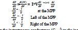 |
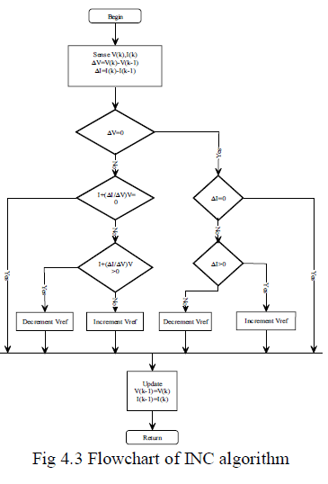
| The MPP can be tracked by comparing the instantaneous conductance (Gci=I/V ) to the incremental conductance as shown in the flowchart (Fig 4.2) and simulation diagram(Fig 4.4) Vref is the reference voltage for which the PV panel is forced to operate at the MPP, Vref = VMPP. Once the MPP is reached, the operating point is maintained, unless a change in Δ is observed, indicating a change in atmospheric conditions and therefore the MPP. The algorithm increases or decreases Vref to track the new MPP. |
 |
 |
H-BRIDGE CASCADED MULTILEVEL INVERTER |
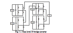
| A comparative study of different topologies of MLI for producing the same five-level output is available in the literature. The topology presented in this paper employs multi string solar cell to generate an equal step nine level output. The proposed inverter consists of four H-bridges per phase as shown in Fig 5.1. Each H-bridges are connected to its solar strings whose value is maintained at 0.25Vdc. By appropriately opening and closing the switches of H1,H2,H3,H4 the output voltage V0 can obtained Vdc,0.75Vdc,0.5Vdc,0.25Vdc as for negative cycle also, and the cascaded output is shown by the simulation part. The capacitor voltage is sensed and fed to an op-amp comparator. The comparator output is given to the FPGA processor to regulate the capacitor voltage. |
 |
SIMULATION AND RESULTS |
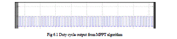
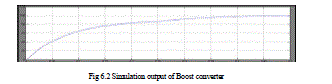
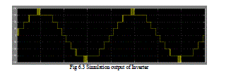
| The flowchart of the incremental conductance and perturb and observe MPPT algorithm has been implemented in Matlab/ Simulink. The simulation results of the MPPT pulse width modulated output as shown in fig 6.1.In this pulse has various instantaneous width depends upon the solar power output. This pulse used to stimulate the power MOSFET of the boost converter. Fig 6.2 shows the Output voltage of the boost converter. It gets the input from solar strings(each string produce 20V) and it improves the voltage level according to the width of the pulse. Boost converter produce 50V output to the Inverter. The cascaded H-bridge multilevel inverter has four bridge network, according to Switching sequence of inverter switches it produce Nine level staircase sinusoidal output voltage. |
 |
 |
OUTPUT WAVEFORM OF INVERTER TIME(S) VS VOLTAGE(V) |
 |
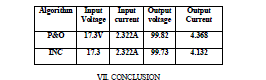
| TABLE 1 |
| Comparative results of P&O and INC algorithm using Boost converter |
| The comparative analysis of both MPPT algorithms were discussed by following Table. |
 |
CONCLUSION |
| Thus the study presents an experimental comparison of the maximum power point tracking efficiencies of several MPPT control algorithms. The MPPT controller adjusts the duty cycle of the boost converter on the event of any change in the irradiance to deliver maximum power possible. Additionally the cascaded multilevel inverter is also implemented here, the performance of multilevel inverter was compared based on the two mostly used MPPT algorithms. Even though the P&O and INC method tracks the maximum power under varying atmospheric condition, the P&O method tracks the maximum power efficiently than INC method. |
References |
|