Keywords
|
| quadrotor; hovercraft; unmanned aircraft vehicle; UVA; PID control; coastal observations |
INTRODUCTION
|
| Recently, coastal areas have been damaged by climate change due to global warming and natural disasters such as storms, tidal wave and oil spill by marine accidents on the shore. Thus it is necessary to investigate disasters for damage compensation and to make measures to prevent the recurrence of an accident. But there is a variety of limitations to universal coverage of observations. Most of observations to implement natural disaster prevention and management measures were accomplished by fixed equipment with limitation of real-time interaction from disaster sites. To collect a variety of information in the affected regions, real-time moving pictures should be offered to disaster main center from the sites. For this reason, unmanned aircraft vehicles based on multi-rotor have recently been studied [1] [2] [3]. |
| A hovercraft, also known as an air-cushion vehicle or ACV, is a craft capable of running on almost every surface such as ground, water surface, mud, sands, grits, weeds etc. Hovercraft use blowers to produce a large volume of air below the hull that is slightly above atmospheric pressure. The pressure difference between the higher pressure air below the hull and lower pressure ambient air above it produces lift, which causes the hull to float above the running surface. For stability reasons, the air is typically blown through slots or holes around the outside of a disk or oval shaped platform, giving most hovercraft a characteristic rounded-rectangle shape. Typically this cushion is contained within a flexible "pocket", which allows the vehicle to travel over small obstructions without damage [4] [5]. Hovercraft has big advantage of offering an effective transport system for high-speed service on water and land, leading to widespread developments for military vehicles, search and rescue, and commercial operations. |
| In this study, we designed an unmanned quadrotor hovercraft which has two advantages over both hovercraft capable of moving over water and land and quadrotor having stable hovering and motion control and precise landings in the target area [6]. Because the designed quadrotor hovercraft can be operated in the air or on the see, it can effectively observe and manage fishfarm and mud flat in coastal region with low-cost and short-term. In this paper, we used the classical PID control in order to stabilize the electric motor craft. And we conducted vertical and horizontal flight test to perform motion and rotation control of the quadrotor hovercraft. Also we analyzed the characteristics of roll, pitch, yaw data obtained from four sensors to know influence by disturbance in hovering flight and the characteristics of X-Y position data and altitude data obtained from GPS in hovering flight. |
DESIGN OF QUADROTOR HOVERCRAFT
|
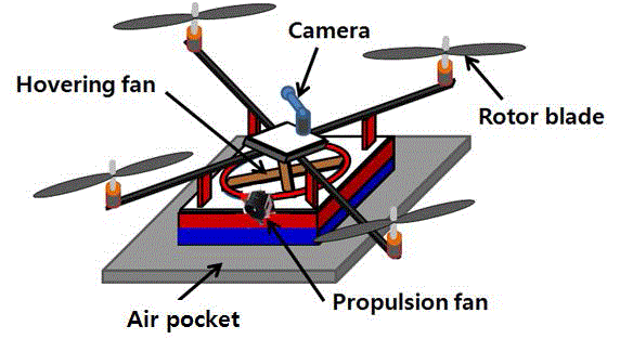
| The purpose of this study is to develop the unmanned aircraft available for coastal observations, which is capable of operation on water and land, VTOL (vertical take-off and landing), hovering, autonomous navigation. The overall structure of quadrotor hovercraft designed in this study is shown in Fig. 1. The quadrotor hovercraft is consisted of four rotors which are attached to the end point of a "+" shaped fuselage. The axis to which each rotor is attached needs to have mechanical hardness because a motor is directly connected. The aircraft frame axis and rotors must be symmetric and equilibrium. Each rotor must have a fixed pitch angle, which generates lift by pushing down the air downward. Additionally, the force to control each rotor's rotation speed and torque is able to implement 6-DOF movement [7]. |
| The hovercraft located underneath the quadrotor aircraft has high-speed electric brushless DC motor (Rimfire .25, GPMG4675) and hovering fan in the centre of the hull for floating above the running surface. The driving motor consists of ducted pan and servomotor is installed on the middle of the back of the hull for propulsion and change of direction of the hull. The hovering fan which is installed on the brushless motor pushes the air down to the bottom of the hull by high rotation and the air is sent to the air pocket. And then the hovercraft can lift and fly above the ground and water by the reacting force. At this state, the hovercraft can move forward by operation of the propulsive ducted fan and can change the moving direction by control the angle of the servomotor [8]. For coastal observations, a camera to recode in real-time is installed on the top of the quadrotor as shown in Fig. 1. |
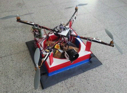
| Fig. 2 shows the prototype of the fabricated quadrotor hovercraft vehicle. The specifications of the prototype vehicle is described in Table 1. The weight of the quadrotor aircraft was 1.2 ? and the weight of the hovercraft was 1.4 ? and the total weight of the vehicle was 2.6 ?. The quadrotor hovercraft was fabricated by using aluminum rods as materials to fix the rotor and the whole weight of the body was designed so that it would not exceed 3 ? to increase the vehicle’s mobility and minimize its battery consumption. They are powered by high-capacity, high-discharge Lithium Polymer batteries and the body of the hovercraft was designed with rectangular shape and the size was 0.4m×0.4m. Aircraft plywood and compressing styrofoam were used as materials of the body of the hovercraft for hardness and lightweight. The size of the air pocket underneath the hovercraft was 0.6m×0.6m. The total height of the vehicle was 0.45m when the pocket remains inflated throughout operation due to continued supply of air through hovering fan delivering a constant mass flow rate. Thus, the hovering height by which the vehicle is lifted up is affected by the inflation of the air pocket. |
CONFIGURATION OF CONTROL SYSTEM
|
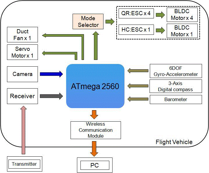
| The vehicle was operated by control signal sent from R/C transmitter. Fig. 3 shows block diagram of flight control system of the quadrotor hovercraft. In order to obtain data from sensors and to stabilize rotors, a controller is required. As a controller in the vehicle, ATmega2560 and APM2.0 board were used. |
| APM2.0 board is equipped with a tri-axial gyro sensor, a tri-axial accelerometer sensor, a tri-axial geomagnetic sensor, a barometric pressure sensor and GPS. The mode selector for selection between quadrotor flight mode and hovercraft flight mode is connected to the board. The controller receives attitude data from a sensor through I2C communication. After data processing, it generates a PWM signal and controls rotation speed of the rotor to manage the vehicle’s motion. And a wireless communication module (Parani-ESD200) was used for transmitting real-time sensor data to PC. As a rotor for propulsion and high power efficiency of quadrotor vehicle, a brushless DC motor (FlyCam925), which maintenance is almost not required, was used. For control of constant speed velocity of rotor, SBEC 20A of FlyCam was adopted as an electronic speed control (ESC). The sensor module included a 6-axis gyroaccelerometer (MPU-6000), which combines a 3-axis gyroscope for measurement of angular velocity and a 3-axis accelerometer for measurement of acceleration value of each axis, and 3-axis geomagnetic sensor (HMC-5883L) to detect direction and barometer (MEAS MS5611) to measure altitude. And the measured real-time images from wireless camera were sent to PC through MCU (ATmega2560). |
| The flight control signal of the quadrotor hovercraft was directly transmitted by R/C transmitter. When the mode selector was chosen as QR mode, the vehicle was operated for quadrotor flight by control of four rotors and when the mode selector was chosen as HC mode, the vehicle was operated for hovercraft flight by control of one hovering fan and one ducted fan and servomotor. Fig. 4 shows the direction testing of the ducted fan by control of servomotor. The direction of the ducted fan was able to be controlled in the range from -90° to +90°. |
FLIGHT EXPERIMENTS
|
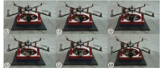
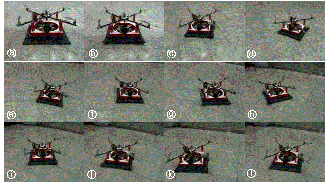
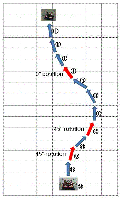
| The flight experiment of the vehicle was performed in relatively spacious room without obstacles. Fig. 5 shows the flight results of the hovercraft. First of all, the control system was selected in HC mode (Fig. 5?). The vehicle was able to lift above the floor by operating hovering fan and then the vehicle moved straight forward by operating the ducted fan (Fig. 5?). When the direction of the ducted fan was changed to +45° direction by controlling servomotor, the vehicle turned right and moved forward (Fig. 5?,?). For direction change, when the ducted fan was changed to - 45° direction, the vehicle turned left and moved forward (Fig. 5?,?,?,?). Finally, when the ducted fan changed in the original direction (0°), the vehicle rotated right and moved in the straight line as shown in Fig. 5?∼? |
| Fig. 6 shows two-dimensional flight path tracing of the hovercraft. The designed hovercraft operated the same as flight properties of the typical hovercraft. As the hovering fan was operated, the hovercraft lifted above the floor and then it moved forward when the ducted fan was operated. Also as the servomotor turned the direction of the ducted fan, the hovercraft could change the expected flight path. |
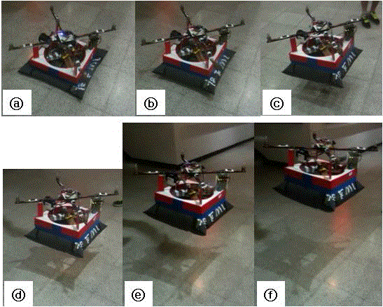
| Fig. 7 shows vertical flight experiments of the quadrotor vehicle. If a pilot firstly selected QR mode in the R/C transmitter, four rotors on the corner of the quadrotor frame were operated. Then the vehicle made flights while changing the altitude. Fig. 7? means the controller settings before flight and Fig. 7? is the flight starting when four rotors was operated. Fig. 7? is the floated vehicle up to 0.2m high from the floor. Fig. 7? is 0.4m high and Fig 7? is 0.6m high and Fig. 7? is 0.8m high. We could confirm the vehicle lifted up to 1.4m high because of the limited testing room. |
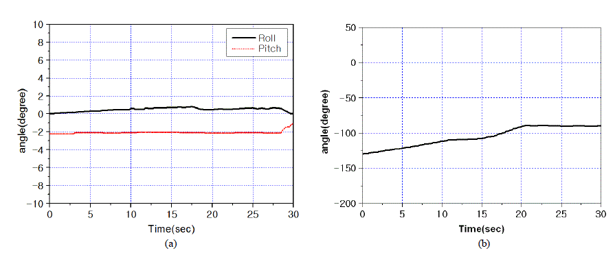
| For checking flight stability of the vehicle, the hovering test of the vehicle was conducted in the outdoors. Fig. 8 shows roll, pitch and yaw data while the vehicle was hovering at 1m altitude. After the vehicle was stabilized for 60 seconds, we analyzed the data gained from the 6-axis gyro-accelerometer for 30 seconds. As shown in Fig. 8(a), the angle data of 6-axis gyro-accelerometer changed according to motion change while hovering of the vehicle. The roll data was changed about 0.9° and the pitch data was changed about 0.2°. Around the 28-second, we can see the abrupt change of roll and pitch data. The reason was that the pilot turned off the hovering operation of the vehicle. Fig. 8(b) shows the change of yaw data. the yaw data changed with the maximum of 40° over 30 seconds. It was caused by that the balance of the vehicle body was not good. Although the yaw data has nothing to do with hovering, for stability of the motion control, it is necessary to complement the vehicle. From these results, we knew that the hovering functions of the vehicle were stable. |
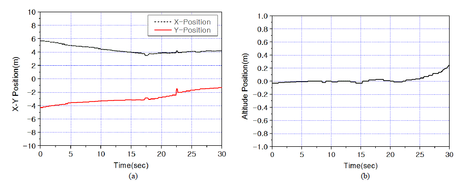
| Fig. 9 shows the position data from GPS at the hovering test of the vehicle. While the vehicle was hovering at 1m height, the vehicle was stabilized for 60 seconds. After that, we analyzed the data gained from GPS for 30 seconds. Fig. 9(a) shows x-axis and y-axis data according to position change while hovering of the vehicle. The movement of the vehicle was 2m at x-axis and 3m at y-axis. As shown in Fig. 9(b), the altitude change of the vehicle was about 0.25m. Because the test was conducted in the outdoors, the vehicle was affected by the wind and thus the position change occurred in the XY-plane. As we analyzed the motion and position characteristics of the vehicle, it is necessary to manufacture the vehicle body using 3D printing technique for exact balance of the body. If we study various algorithms for removing the disturbance of flight, the optimum flight characteristics would be able to be obtained [9] [10]. |
CONCLUSION AND FUTURE WORK
|
| In this paper, we designed and manufactured the quadrotor hovercraft capable of operation over water and land and in the air. Because the proposed vehicle has two merits of the quadrotor UAV and the hovercraft, it can effectively observe and manage fishfarm and mud flat in coastal area with low-cost and short-term. After the vehicle obtained information from four sensors and GPS through I2C communication, the controller generated PWM signal for motion control and then the motion control of the vehicle was accomplished by controlling rotation rates of the motors. The selector was applied to select the flight operation mode between quadrotor flying and hovercraft flying. We confirmed that the operation characteristics were stable from the results of vertical flight test of the quadrotor and horizontal flight test of the hovercraft. Also the possibility of UAV application was acknowledged by experimental analysis of position change in the XY-plane and altitude change. Through further study, if the exact manufacture of the vehicle body and various algorithms for removing the disturbance of flight were studied and improved, the proposed vehicle would be able to apply for coastal observation over water and ground and in the air. |
Tables at a glance
|
 |
| Table 1 |
|
Figures at a glance
|
 |
 |
 |
 |
 |
| Figure 1 |
Figure 2 |
Figure 3 |
Figure 4 |
Figure 5 |
|
 |
 |
 |
 |
| Figure 6 |
Figure 7 |
Figure 8 |
Figure 9 |
|
References
|
- Li, C. C., Zhang, G. S., Lei, T. J. and Gong, A. D., "Quick Image-Processing Method of UAV without Control Points Data in Earthquake Disaster Area", Trans. Nonferrous Met. Soc. China, Vol. 21, pp. 523-528, 2011.
- Haitao, X. and Lei, T., "Development of a Low-Cost Agricultural Remote Sensing System based on an Autonomous Unmanned Aerial Vehicle(UAV)", Biosystems Engineering, Vol. 108, pp. 174-190, 2011.
- Yang, Y. Q., Liu, F. Q., Wang, P., Luo, P. T. and Liu, X. F., "Vehicle Detection Methods from an Unmanned Aerial Vehicle Platform", Proceedings of Int. Conf. Vehicular Electronics and Safety, pp. 411-415, 2012.
- Syozo, K., Hiromichi, A. and Takumi, M., "First-Aid Transportation by Hovercraft in a Disaster", Natural Hazards, Vol. 29, pp. 553-564, 2003.
- http://en.wikipedia.org/wiki/Hovercraft
- Samir, B. D., "Design and Control of Quadrotors with Application to Autonomous Flying", Phd Thesis, Autonomous Systems Laboratory, Swiss Federal Institute of Technology, 2007.
- Rich, M., “Model Development, System Identification and Control of a Quadrotor Helicopter", M.S. Thesis, Iowa State University, 2012.
- Wang, C. C. and Lee, T. E., "Design of an Autonomous Remote Control Hovercraft with Image Recognition Technology", Indian J. of Eng. & Mat.Sci., Vol. 20, pp. 183-190, 2013.
- Jo, S. B., Jang, S. A and Choi, K. Y., "Analysis on Dynamic Characteristics and LQR Control of a Quadrotor Aircraft with Cyclic Pitch", J. of The Korean Society for Aeronautical and Space Sciences, Vol. 41, No. 3, pp. 217-225, 2013.
- Lim, J. G. and Jung, S., "Experimental Studies of Attitude Control of a Quad-rotor System using a Time-delayed Controller", J. Institute of Control, Robotics and Systems, Vol. 20, No. 4, pp. 381-388, 2014.
|