ISSN ONLINE(2278-8875) PRINT (2320-3765)
ISSN ONLINE(2278-8875) PRINT (2320-3765)
Dr.B. Suryakanth1, Dr.S. N. Mulgi2
|
| Related article at Pubmed, Scholar Google |
Visit for more related articles at International Journal of Advanced Research in Electrical, Electronics and Instrumentation Engineering
This paper presents the experimental investigations carried out for obtaining dual band operation of rectangular microstrip antenna by using aperture coupled feeding technique. The antenna resonates for two resonant frequencies at 11.36 GHz and 14.26 GHz with minimum return losses of –22.97 dB and –22.24 dB respectively. The antenna operates at two bands BW2 and BW3. These two bands are due to independent resonance of patch and double U-slots which are excited through H-coupling aperture. The lower resonant frequency f1 is the fundamental resonance of the rectangular patch. The second resonant frequency f2 is due to current along the edges of double U-slots of aperture coupled double U-slot rectangular microstrip antenna (ADUSRMSA). The impedance bandwidths of BW2 and BW3 are found to be 23.87 % and 21.68 % respectively. This technique also enhances the gain to 6.31 dB which is 1.19 times more than the gain of conventional rectangular microstrip antenna (CRMA) and minimizes the cross polar power level to -10.14 dB down compared to co-polar power level. The enhancement of bandwidth, gain and reduction of cross-polar power level does not affect the nature of broadside radiation
Keywords |
| Microstrip, Dual band, Aperture coupled, Slots |
INTRODUCTION |
| The microstrip antennas (MSAs) are widely used for the last few years due to their attractive features such as light weight, low volume, ease in fabrication and low cost [1]. However, two major disadvantages coupled with MSAs are low gain and narrow bandwidth. The conventional MSAs have typical bandwidth nearly 2 to 5% [1-2], which restricts their many useful applications. Numbers of studies have been reported in the literature for enhancing the bandwidth [3- 6] and gain [7-8]. Further in modern communication systems, such as satellite links or radar communications, dual band MSAs are more striking as they avoid use of two separate antennas for transmit/receive applications. The dual band antennas are realized by many methods such as by using shorting pins on the patch [9], using aperture coupled parallel resonators [10], reactively loaded patch [11] etc. In this presentation enhanced dual band antenna is realized by using aperture coupled feeding technique. Further the proposed antenna is also capable for the enhancement of gain and reduction of cross polar power level by placing double U-slot on the patch and by feeding it through aperture coupled technique. The enhancement of bandwidth, gain and reduction of cross-polar power level does not affect the nature of broadside radiation characteristics |
DESCRIPTION OF THE ANTENNA GEOMETRY |
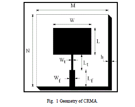
| The art work of proposed antennas are developed using computer software AutoCAD and are fabricated on low cost glass epoxy substrate material of thickness h=1.6 mm and permittivity r=4.2. The CRMA has been designed using the equations available in the literature [1]. Figure 1 show the geometry of CRMA, which is designed for the resonant frequency of 9.4 GHz. The antenna is fed by using microstripline feeding. This feeding has been selected because of its simplicity and it can be simultaneously fabricated along with the antenna element. Figure 1 consists of a radiating patch of length L and width W, quarter wave transformer of length Lt and width Wt used between the patch and 50 microstripline feed of length Lf and width Wf. At the tip of microstripline feed, a 50 coaxial SMA connector is used for feeding the microwave power. |
 |
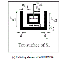
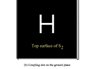
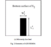
| Figure 2 shows the geometry of ADUSRMSA. The radiating element is etched on the top surface of substrate S1 as shown in Fig. 2 (a). The length Lu1 and width Wu1 of the outer U-slot are λ0/5.26 and λ0/21.27 respectively. The length Lu2 and width Wu2 of the inner U-slot are chosen as λ0/11.02 and λ0/15.45 respectively. The outer U-slot is placed at a distance d1 of λ0/31.91 from the non-radiating edges of the patch. Further the inner U-slot is placed at a distance d2 which is λ0/15.49 from the lower horizontal side of the patch. The extended arm of the inner U-slot is EU. The gap between the two arms is G. The copper layer on the bottom surface of S1 is removed. The H-coupling aperture is etched on top surface of substrate S2 which is the ground plane as shown in Fig. 2 (b). |
 |
 |
 |
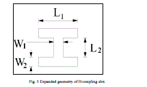
| The geometry of the coupling H-slot is as shown in Fig. 3. This aperture has been selected because it is more effective in coupling the power to the patch etched on the top surface of S1 when compared to any other aperture [12]. The length of each horizontal arm in H-slot is L1 and width W1. The length and width of vertical arm of this slot are L2 and W2 respectively as shown in Fig. 3. Table1 and Table 2 show the designed parameters of the proposed antennas in mm. |
 |
 |
EXPERIMENTAL RESULTS |
| The CRMA is designed and fabricated for 9.4 GHz of frequency which is standard or test frequency of X-band. The impedance bandwidth over return loss less than −10 dB is measured from 8 to 12 GHz of frequencies. The variation of return loss versus frequency of CRMA is as shown in Fig. 4. |
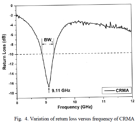 |
| From this figure, it is seen that the antenna resonates at 9.11 GHz of frequency with minimum return loss of −16.79 dB. The impedance bandwidth (BW1) of CRMA is calculated by using equation (1) and is found to be 4.40 %. |
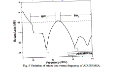
| Where, fH and fL are the upper and lower cut-off frequency of the band respectively when its return loss becomes -10dB and fc is the centre frequency between fH and fL.. The variation of return loss versus frequency of ADUSRMSA of Fig. 2 is as shown in Fig. 5. From this figure, it is seen that, the antenna resonates for two modes of frequencies at f1=11.36 GHz and f2=14.26 GHz with minimum return losses of –22.97 dB and –22.24 dB respectively. The antenna operates for two bands BW2 and BW3. These two bands are due to independent resonance of patch and double U-slots which are excited through H-coupling aperture [12]. The lower resonant frequency f1 is the fundamental resonance of the rectangular patch. The second resonant frequency f2 is due to current along the edges of double U-slots of ADUSRMSA. The impedance bandwidth BW2 and BW3 are found to be 23.87 % and 21.68 % respectively. |
 |
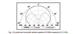
| The co-polar and cross-polar radiation patterns of CRMA are measured in its operating band. The typical radiation patterns measured at 9.11 GHz are as shown in Fig. 6. From this figure, it is seen that, the pattern is broadsided and linearly polarized. The half power beam width (HPBW) measured from Fig.6 is found to be 760. The cross-polar power level is −10.14 dB down compared to co-polar power level. The cross polar power level usually -10 dB down or below with respect to co-polar power level normally indicates the broadside nature of radiation. The gain of CRMA is found to be 5.26 dB. |
 |
| A typical co-polar and cross-polar radiation pattern of ADUSRMSA measured at 11.36 GHz is as shown in Fig. 7. From this figure, it is seen that, the pattern is broadsided and linearly polarized. |
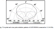 |
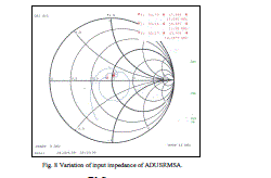
| The HPBW measured from Fig 7 is found to be 68.760. The cross-polar power level is −10.14 dB down compared to co-polar power level. The gain of ADUSRMSA is found to be 6.31 dB which is 1.19 times more than the gain of CRMA.The variation of input impedance of this antenna measured on VNA is as shown in Fig. 8. It is clear from this figure that, the input impedance is very close to the characteristic impedance of 50 Ω at the two resonant frequencies f1 and f2. This shows an excellent impedance matching. The loop around the centre of Smith chart indicates the wideband nature of the antenna. |
 |
CONCLUSION |
| From the detailed experimental study it is concluded that the use of aperture coupled technique is effective in obtaining dual band operation and enhancing the impedance bandwidth of CRMA. The impedance bandwidths of BW2 and BW3 are found to be 23.87 % and 21.68 % respectively. This technique also enhances the gain to 6.31 dB which is 1.19 times more than the gain of CRMA and minimizes the cross polar power level to -10.14 dB down compared to co-polar power level. The enhancement of bandwidth, gain and reduction of cross-polar power level does not affect the nature of broadside radiation characteristics. The proposed antennas are simple in design and fabrication and they use low cost substrate material. These antennas may find application in communication system operating in X & Ku band frequencies. |
ACKNOWLEDGEMENT |
| The authors would like to thank Dept. of Science & Technology (DST), Govt. of India, New Delhi, for sanctioning Vector Network Analyser to this Department under FIST project. |
References |
|