International Journal of Advanced Research in Electrical, Electronics and Instrumentation Engineering
ISSN ONLINE(2278-8875) PRINT (2320-3765)
ISSN ONLINE(2278-8875) PRINT (2320-3765)
B. Pal1, B. Dey2, C. Debnath3, S. Banerjee4
|
| Related article at Pubmed, Scholar Google |
Visit for more related articles at International Journal of Advanced Research in Electrical, Electronics and Instrumentation Engineering
Many industrial applications require variable speed drives. In recent days many researchers have focused on Pulse Width Modulation (PWM) based multilevel inverter drives for inverter quality improvement. Inverter performances are evaluated by calculating overall THD of output signals. In this paper a new multilevel inverter topology is described with reduced number of switches. Different Sinusoidal PWM schemes (PD, POD, APOD) has been employed to the reduced switch inverter and a comparative performance is analyzed of the inverter in terms of Total Harmonic Distortion. The reduced switch multilevel inverter has been designed and different SPWM schemes have been developed in MATLAB SIMULINK environment.
Keywords |
| SPWM, Multilevel Inverter, THD, SIMULINK, PDPWM, PODPWM, APODPWM. |
INTRODUCTION |
| In recent days power quality of industrial inverters has become an important issue. To improve power quality of industrial drives multilevel inverters are introduced [1]. Multilevel inverters are employed in high power and medium voltage applications. In one hand Multilevel inverters increase voltage level which makes its use in medium voltage applications, on the other hand with the increase in level of inverter, overall THD of the inverter output variables reduce, which improves inverter quality. |
| In this paper, a reduced switch multilevel inverter is proposed, which uses less number of controlled switches than that of conventional multilevel inverters. Thus overall cost of the inverter is reduced. Less number of inverter switches also reduces the complexity associated with the generation of SPWM signals [2]. Here, PDPWM, PODPWM and APODPWM methods are used to generate gate signals for inverter switches. A comparative performance has been analysed of the proposed multilevel inverter with different SPWM techniques [3]. This paper shows variation of THD of inverter output variables with the variation in Modulation Index, carrier frequency, level of inverter. |
LITERATURE REVIEW |
| 1. John N. Chiasson, Keith J. McKenzie introduced a method to compute the switching angles in a multilevel inverter to produce required fundamental voltage at reduced higher order harmonics [1]. It is shown in this paper that the theory of symmetric polynomials can be exploited to reduce the degree of polynomial equations that must be solved which considerably reduces computational burdens. A novel method is used in this paper to eliminate harmonics in multilevel inverters using symmetric polynomials and resultants. |
| 2. |
| 3. Biswamoy Pal, Reetam Mondal proposed a new multilevel inverter topology with reduced numbers of switches than that of a conventional multilevel inverter [2,7]. This paper also described a method for generating PDPWM signal in order to generate sinusoidal output voltage with fewer harmonic. The variation in overall THD of inverter output voltage is also shown in this paper with the variation in levels of MLI at different carrier frequencies. |
| 4. Rajesh Kumar Ahuja, Amit Kumar proposed a method to control three phase multilevel inverters with SPWM technique feeding balanced load [3]. Here, APODPWM technique is used for SPWM signal generation. This paper shows variation in inverter performance in terms of THD of output voltage for different levels at different loads. |
| 4. Rajesh Kumar Ahuja, Amit Kumar proposed a method to control three phase multilevel inverters with SPWM technique feeding balanced load [3]. Here, APODPWM technique is used for SPWM signal generation. This paper shows variation in inverter performance in terms of THD of output voltage for different levels at different loads. |
| 6. Jose Rodriguez, Jih – Sheng lai, Fang Zheng Peng made a survey on different types of configurations of multilevel inverters like diode clamped inverter, capacitor clamped inverter and cascaded multicell H- bridge inverters [6]. This paper also presented most relevant control strategies of the above mentioned families of multilevel inverters. |
| 7. M.S.Aspalli, Anil Wamanrao proposed a method for Sinusoidal Pulse Width Modulation (SPWM) With Variable Carrier Synchronization for Multilevel Inverter Controllers [8]. In this paper different carrier based sinusoidal PWM techniques are carried out and their comparative performance has been analyzed. |
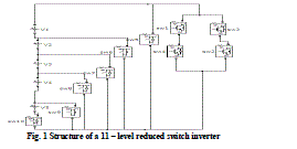
STRUCTURE OF PROPOSED REDUCED SWITCH 1 – Φ MULTILEVEL INVERTER (MLI) |
| Multilevel inverters use numbers of power semiconductor controlled switches to generate stepped waveform. A two level inverter generates an output of two levels; three level inverter generates an output of two levels and so on. If level of inverter goes on increasing the output voltage of inverter gets more steps generating a staircase waveform which is a replica of sine waveform. Thus by increasing levels of inverter overall THD of inverter output voltage gets reduced and power quality is improved. Besides improving power quality, multilevel inverters also generate high voltage, which makes its use in medium voltage high power applications. But there is a problem associated with multilevel inverters. More number of switches increases the drive cost. Also complexity associated with SPWM signal generation for more switches is increased. This paper presents a multilevel inverter uses less number of power switches than that of a conventional multilevel inverter for same level of output voltages. Thus the proposed inverter reduces cost of inverter and also complexity with SPWM signal generation for this inverter is reduced [4 - 6]. |
| The figure below shows general structure of 11 – level reduced switch inverter. A number of voltage sources having equal magnitudes are used. Number of sources for a particular MLI along with proper gating signal decides level of the inverter output voltage. Number of switches required to generate certain levels of output voltage depends on level of MLI. |
| In the proposed structure of MLI two pair of diagonal switches (sw1,sw2,sw3,sw4) are used, which decides the polarity of output voltage. The switches sw1 & sw2 are complimentary of sw3 & sw4. That is, If sw1 & sw2 are ON, sw3 & sw4 are OFF and output voltage will be positive, otherwise output voltage will be negative. By controlling other switches (sw5, sw6....) are used to decide output voltage level. If sw5 is ON, output voltage is 0.If sw6 is ON, output voltage is +Vdc. If sw7 is ON, output voltage is +2Vdc and so on [7]. |
 |
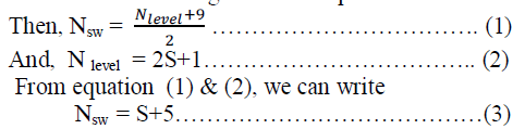
| In this paper, a generalised Multilevel structure is proposed. The level of proposed multilevel inverter can be increased as desired based on the following formulas. |
| In this paper, a generalised Multilevel structure is proposed. The level of proposed multilevel inverter can be increased as desired based on the following formulas. |
| Let, Total number of switches required = Nsw |
| Number of levels of MLI = N level |
| Number of voltage sources required = S |
 |
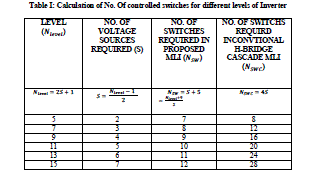
| The above equations are used to design a multilevel inverter of any level. The table below shows number of switches and voltage sources required for different levels of MLI. |
 |
DIFFERENT LEVEL SHIFTEDSPWM TECHNIQUES FOR MULTILEVEL INVERTER |
| In SPWM method the modulating signal is sine wave and triangular wave is carrier signal. This two signals are then compared to generate gating signals for controlled switches. There are different level shifted SPWM techniques for multilevel inverters – (i) Alternate Phase Opposition Disposition PWM (APODPWM) (ii) Phase Opposition Disposition PWM ( PODPWM) (iii) Phase Disposition PWM (PDPWM). In all cases number of carrier signals used is (Nlevel - 1) [8 - 9]. |
| The power quality of inverter output voltage is affected by Modulation Index (MI). The MI for multilevel SPWM inverter can be calculated as follows: |
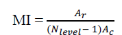 |
| Where, A r = Amplitude of reference signal (Sine wave), Ac = Amplitude of carrier signal (Triangular wave) In all the cases of SPWM techniques shown in above figure, the triangular carrier signals are level shifted. Each carrier signal has same amplitude and have same frequencies. The frequency must be an integer multiple of reference signal frequency to maintain synchronism. |
APODPWM Technique: |
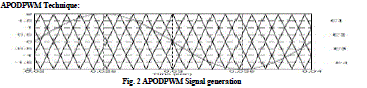 |
| In APODPWM technique alternate carrier waves are out of phase with each other. That is, C1 & C3 are in same phase and C2 & C4 are in same phase, but out of phase with C1 & C3. The modulating frequency is 50 hz and carrier frequency is chosen to be 1 Khz. The above figure shows SPWM signal generation scheme for a five level inverter. |
PODPWM Technique: |
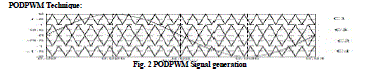 |
| In PODPWM technique all carrier waves above reference level (zero level) are in same phase with each other. That is, C1 & C2 are in same phase and all carrier waves below reference level (zero level) are in same phase, That is, C3 & C4 are in same phase, but out of phase from C1 & C2. The modulating frequency is 50 hz and carrier frequency is chosen to be 1 Khz. The above figure shows SPWM signal generation scheme for a five level inverter. |
PDPWM Technique: |
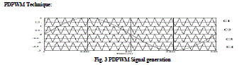 |
| In PDPWM technique all carrier waves are in same phase with each other. That is, C1, C2, C3, C4 are in same phase with each other. The modulating frequency is 50 hz and carrier frequency is chosen to be 1 Khz. The above figure shows SPWM signal generation scheme for a five level inverter. |
SIMULATION RESULTS |
| Simulation results show variation of overall THD of inverter output voltage for different levels using different level shifted PWM techniques for a particular modulation index (MI = 1). |
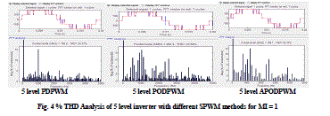
| The figure below shows FFT window of 5 – level inverter output voltage using PDPWM, PODPWM & APODPWM techniques respectively for modulation index 1. It has been observed that PODPWM technique gives the best result among these three level shifted PWM techniques. |
 |
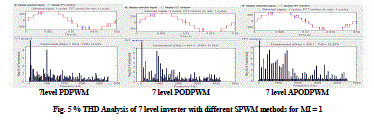
| The figure below shows FFT window of 7 – level inverter output voltage using PDPWM, PODPWM & APODPWM techniques respectively for modulation index 1. It has been observed that PODPWM technique gives the best result among these three level shifted PWM techniques. |
 |
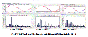
| The figure below shows FFT window of 9 – level inverter output voltage using PDPWM, PODPWM & APODPWM techniques respectively for modulation index 1. It has been observed that PDPWM technique gives the best result among these three level shifted PWM techniques. |
 |
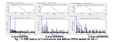
| The figure below shows FFT window of 11 – level inverter output voltage using PDPWM, PODPWM & APODPWM techniques respectively for modulation index 1. It has been observed that PODPWM technique gives the best result among these three level shifted PWM techniques. |
 |
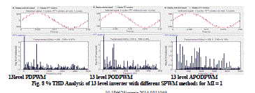
| The figure below shows FFT window of 13 – level inverter output voltage using PDPWM, PODPWM & APODPWM techniques respectively for modulation index 1. It has been observed that APODPWM technique gives the best result among these three level shifted PWM techniques. |
 |
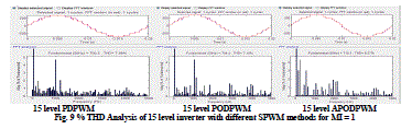
| The figure below shows FFT window of 15 – level inverter output voltage using PDPWM, PODPWM & APODPWM techniques respectively for modulation index 1. It has been observed that PODPWM technique gives the best result among these three level shifted PWM techniques. |
 |
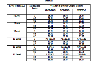
| Simulation results show variation of overall THD of inverter output voltage for different levels using different level shifted PWM techniques for different modulation index. The whole experiment has been carried out in MATLAB/ SIMULINK environment and the obtained results are given in the following table. This table shows variation of inverter performance in terms of THD of output voltage for different levels at different modulation index using different level shifted PWM techniques. |
 |
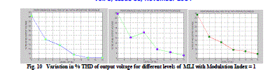
| These graphs show variation of inverter performance in terms of THD of output voltage for different levels for modulation index 1 using different level shifted PWM techniques. |
 |
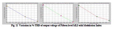
| These graphs show variation of a 15 level inverter performance in terms of THD of output voltage for different modulation index using different level shifted PWM techniques. |
 |
CONCLUSION |
| In this paper a general structure of single phase multilevel inverter with reduced number of switches with SPWM techniques has been introduced and the performance of the MLI is analysed in MATLAB/SIMULINK environment. It has been seen in this experiment that inverter performance (in terms of % THD of output voltage) is improved if level of inverter is increased. It was also shown that modulation index affects the inverter performance, if MI is increased, the inverter performance improves. Also a comparative study has been analysed for different levels excited with different level shifted SPWM techniques. |
References |
|