Keywords
|
| Proximity coupled, Equilateral triangular, bandwidth, Gain, VSWR and radiation patterns. |
INTRODUCTION
|
| Due to many attractive features and desirable characteristics, the microstrip antennas have gained importance in the modern wireless communication systems as well as an ultimate solution for development of handheld mobile devices in both commercial industries and research academia [1]. The present era of wireless communication, possess many desirable features such as light weight, wide bandwidth, low cost, direct integrability with microwave circuitry [2]. |
| In view of the rapid progress in wireless communication systems, high-gain broadband antennas are of great demand. Even though, microstrip antennas have advantages like low profile and ease of fabrication, their usage is limited by their inherent narrow bandwidth. Various techniques like aperture coupling [3], use of coupled parasites [4], stacking [5] [6], E-shaped patch [7] and modifications in the feed [8]–[10] have been proposed to enhance the bandwidth of microstrip antennas. |
| Basically, a microstrip antenna consists of a planar radiating structure of desired geometrical shape on one side of a dielectric substrate and a ground plane on the other. Commonly used microstrip radiating geometries are rectangular and circular [11]. However, other shapes are also considered depending upon the application. By considering this aspect, a study is carried out by increasing the lengths of the slots in proximity coupled equilateral triangular microstrip antenna. |
ANTENNA DESIGNCONSIDERATION
|
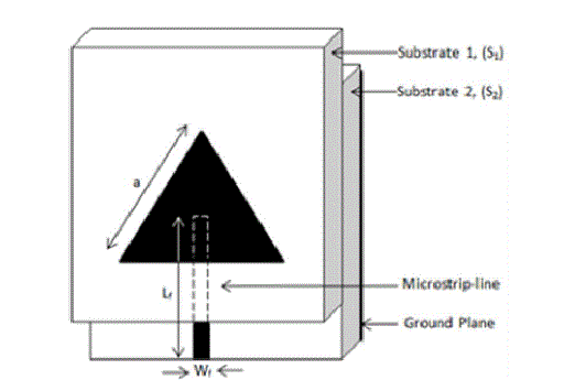
| Fig. 1 shows the geometry of proximity coupled equilateral triangular microstrip antenna (PCETMSA). The proposed antenna is designed for the frequency of 3 GHz using the relations present in the literature for the design of equilateral triangular microstrip antenna. There are numerous substrates that can be used for the design of microstrip antenna and their dielectric constants are usually in the range of 2.2 ≤ εr ≤ 12. The proposed antenna uses a low cost glass epoxy substrate material with a dielectric constant εr= 4.2. The equilateral triangular microstrip patch antenna is made up of side length ‘a’ cm over a substrate S1with substrate thickness ‘h’ cm. The value of ‘a’ is calculated by the equation (1), |
 |
| The microstripline feed of length Lf and width Wf is etched on the top surface of substrate S2. The substrate S2 is placed below substrate S1 such that the tip of the feedline and the centre of the radiating patch coincide one over the other. The bottom surface of the substrate acts as the ground plane. The proposed antenna is designed using the computer software AUTOCAD to achieve better accuracy. The antenna is fabricated using the photolithography process. |
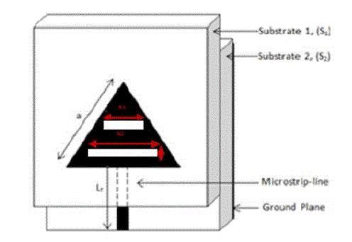
| Further, the design is modified by employing two horizontal I-shape slots on the radiating patch by varying the dimensions of length of the slots and keeping width of the slots constant, which is shown in Fig. 2, where SL1 and SL2 are the length of the slots and SW is width of the slots. All the specifications of the proposed antenna are given in Table. |
RESULTS AND DISCUSSION
|
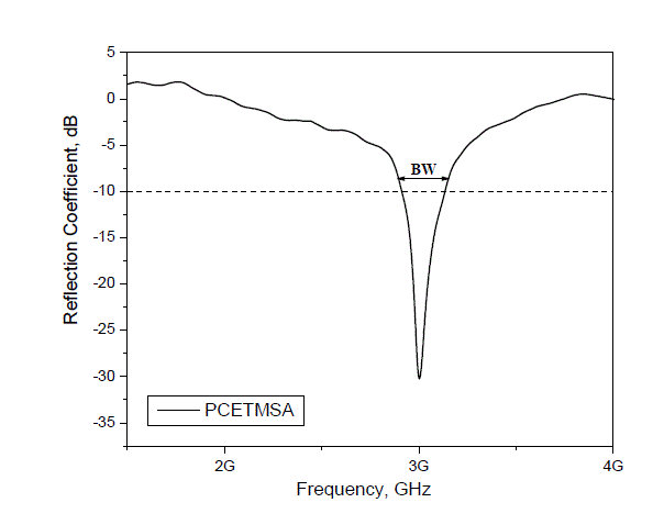
| The impedance bandwidths over return loss less than -10 dB for the proposed antennas are measured.The measurements are taken on Vector Network Analyzer (Rohde & Schwarz, German make ZVK Model No. 1127.8651). The Fig. 3 shows the variation of return loss versus frequency of PCETMSA. It is seen that, the antenna resonates at 3 GHz. The percentage of experimental impedance bandwidth is calculated using the relation is given by equation (2), |
 |
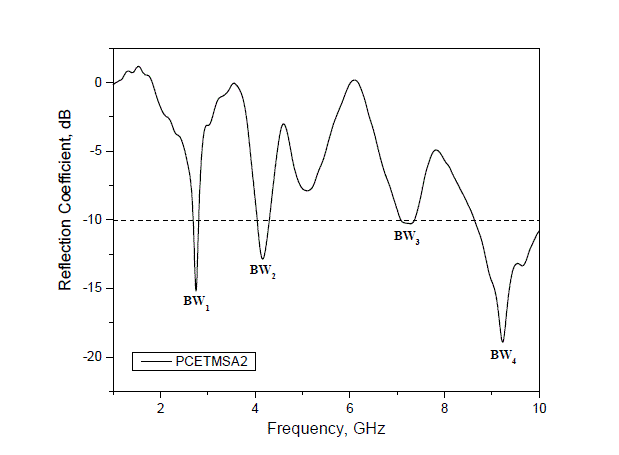
| where f2 and f1 are the upper and lower cut off points of resonating frequency when its return loss reaches -10 dB and fc is a center frequency between f1 and f2. The impedance bandwidth of PCETMSA is found to be 6.97%. The Fig. 4 shows the variation of return loss versus frequency of HISPCETMSA. From this figure it is found that the antenna resonates at quad bands of frequencies f1, f2, f3 and f4 with their respective impedance bandwidths (BW1) 4.74%, (BW2) 6.49%, (BW3) 4.16% and (BW4) 14.77% respectively. The minimum return loss and VSWR measured are tabulated in Table 2. |
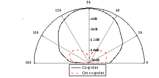
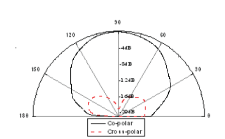
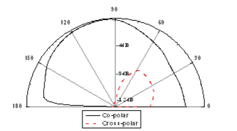
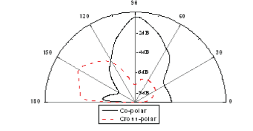
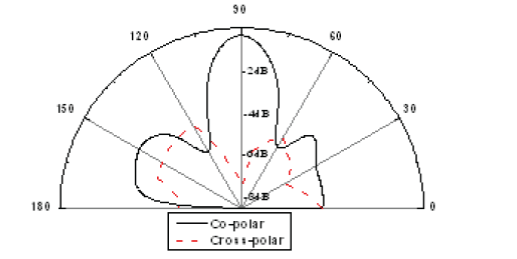
| The X-Y plane co-polar and cross-polar radiation patterns of PCETMSA and HISPCETMSA are measured at their resonating frequencies and are shown in Fig. 5 to Fig. 9. These figures indicate that the antennas show broad side radiation characteristics. Further the calculated HPBW is shown in Table 3. |
| The gain of proposed antenna is calculated using absolute gain method given by the equation (3), |
 |
| where, Pt and Pr are transmitted and received powers respectively, Gt is the gain of the pyramidal horn antenna and R is the distance between transmitting antenna and antenna under test. The gain of the antenna is also tabulated in Table 3. |
CONCLUSIONS
|
| From the detailed experimental study, it is concluded that the antennas are quite simple in design and fabrication. The PCETMSA antenna gives a single frequency band but after loading horizontal I-shape slots i.e. HISPCETMSA resonates for quad operating frequency bands and is quite good in enhancing the impedance bandwidth and gives better gain with broadside radiation patterns at the resonating frequencies. The antenna is also superior as it uses low cost substrate material and finds applications in wireless communication systems such as LTE 2006, IMT and in radar systems. |
ACKNOWLEDGEMENT
|
| The authors express their thanks to the Department of Science and Technology (DST), Govt. of India, New Delhi, for sanctioning Vector Network Analyzer under the FIST Programme to the Department of Applied Electronics, Gulbarga University, Gulbarga |
Tables at a glance
|
|
|
Figures at a glance
|
 |
 |
 |
 |
 |
| Figure 1 |
Figure 2 |
Figure 3 |
Figure 4 |
Figure 5 |
|
 |
 |
 |
 |
| Figure 6 |
Figure 7 |
Figure 8 |
Figure 9 |
|
References
|
- Constantine. A. Balanis “Antenna theory analysis and design”, John Willey, New York, 1997.
- D.M.Pozar, “Microstrip Antennas,” Proceeding, IEEE, Vol. 80, pp.79- 81, January,1992.
- D. M. Pozar and B. Kaufman, “Increasing the bandwidth of a microstrip antenna by proximity coupling,” Electron. Lett., vol. 23, no. 8, pp.368–369, 1987.
- C.K.Aanandan, P.Mohananand and K.G.Nair“Broad-band gap coupled Microstrip antenna, IEEE Trans. Antennas Propag.,vol.38,no.10,pp.1581–1586, Oct. 1990.
- S. D. Targonski, R. B. Waterhouse, and D. M. Pozar, “Design of wide- band aperture stacked patch microstrip antennas,” IEEE Trans.AntennasPropag., vol. 46, no. 9, pp. 1245–1251, Sep. 1998.
- M. A. Martin, B. S. Sharif, and C. C. Tsimenidis, “Probe fed stacked patch antenna for wideband applications,” IEEE Trans. Antennas Propag.,vol. 55, no. 8, pp. 2385–2388, Aug. 2007.
- F. Yang, X.-X. Zhang, Z. Ye, and Y. Rahmat-Samii, “Wide-band E-shaped patch antennas for wireless communications,” IEEE Trans.Antennas Propag., vol. 49, no. 7, pp. 1094–1100, Jul. 2001.
- Y.-X. Guo, M. Y. W. Chia, Z. N. Chen and K.-M.Luk, “Wide-band L-probe fed circular patch antenna for conical-pattern radiation,” IEEETrans. Antennas Propag., vol. 52, no. 4, pp. 1115–1116, Apr. 2004.
- J. Park, H.-g. Na, and S.-h. Baik, “Design of wideband aperture stacked patch microstrip antennas,” IEEE Antennas Wireless Propag. Lett., vol.3, pp. 117–119, 2004.
- C.-L.Mak, H.Wong and K.-m.Luk “High-gain and wide-band single- layer patch antenna for wireless communications,” IEEE Trans. Veh.Technol., vol. 54, no. 1, pp. 33–40, Jan. 2005.
- Ashish Kumar “Rectangular Microstrip patch antenna using L slot structure” International Journal of Research in Electrical and ElectronicsEngineering (IJREEE), Vol. 2, Issue. 2, pp. 15-18, March 2013.
|