ISSN ONLINE(2278-8875) PRINT (2320-3765)
ISSN ONLINE(2278-8875) PRINT (2320-3765)
Swagata Sharma1, Satabdi Kalita1, Himakshi Mishra1, Santanu Sharma2
|
| Related article at Pubmed, Scholar Google |
Visit for more related articles at International Journal of Advanced Research in Electrical, Electronics and Instrumentation Engineering
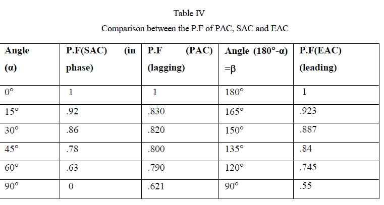
This paper presents the design, simulation and development of a symmetrical angle controlled (SAC) and an extinction angle controlled (EAC) rectifier using MOSFETs for driving a PMDC motor. Using these methods, the power factor can be improved and certain lower order harmonics can be reduced or eliminated. Harmonic analysis of the input current for different extinction angles is also done. The paper also discusses the various performance parameters like power factor and displacement factor of the controlled rectifier. Power factor (PF) for extinction angle, firing angle and symmetric angle at different angles are compared.
Keywords |
| controlled rectifier, power factor, displacement factor, symmetrical angle control, extinction angle control. |
INTRODUCTION |
| One of the power electronics system which are widely used to control an output dc voltage are the controlled rectifiers; where a variable dc voltage is obtained from a fixed dc voltage by methods such as firing angle control, symmetrical angle control and extinction angle control. These types of rectifiers are quite simple and less expensive and are substantially used in dc motor speed control systems, widely used in steel mills, paper mills etc. |
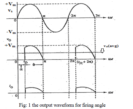
| Studies on phase angle control (PAC) technique for PF improvement have been presented and operation of ac voltage controllers have been explained in details [1-2]. In conventional controllers, the PAC technique can be utilized to control the power flow to the load by varying the firing angle (α) of the thyristor. The firing angle (α) can be measured from the zero crossing of phase voltage [3]. Studies also show that phase control technique is reliable and has the ability to control large amount of power [4]. However, the major setbacks of this technique are that there is retardation of firing angle, lagging of power factor at the input side especially at large firing angles and high and low order harmonic content in both load and supply sides [5-7]. Moreover, it was seen that power flow discontinuity appears at both input and output sides [3]-[4], [8]-[10]. |
| An EAC technique on three phase AC voltage controllers was employed on static load and its significant improvement in input power factor and efficiency over PAC has been presented [11]. Conclusion was drawn that EAC was efficiency effective while the PAC technique involved a huge cost factor. Squirrel cage single phase induction motor was used as dynamic load along with the static load in another study involving the same method to draw comparison with PAC. Improvement in displacement factor was observed in this technique [12]. |
| In this paper, controlled rectifiers using symmetrical angle control (SAC) and extinction angle control method (EAC) has been designed and developed using power MOSFETs. Unlike circuits using thyristors, these circuits do not require an extra commutation circuit, can be easily controlled and have higher switching speeds. Besides, MOSFET has the advantages of the majority carrier device, so it can achieve very high operating frequency. In addition, excellent performance of MOSFET in low voltage makes the device suitable for applications below 200V. |
| The extinction angle control is similar to phase angle control. In phase angle control the conduction starts at the required delay angle (α) and continues until the current reaches zero value naturally while in the EAC the conduction starts at zero crossing of the supply voltage and forced commutated at a certain angle before the next zero crossing (β). Thus in extinction angle controlled rectifiers fundamental component of input current will lead the input voltage [12]. |
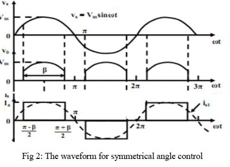
| Therefore, in EAC technique, the displacement factor leads and consequently the power factor leads. In the proposed controlled rectifier, this feature of leading PF is used to simulate a capacitive load. Fig: 1 and Fig: 2 show the voltage and current waveform of the PAC and SAC. |
 |
 |
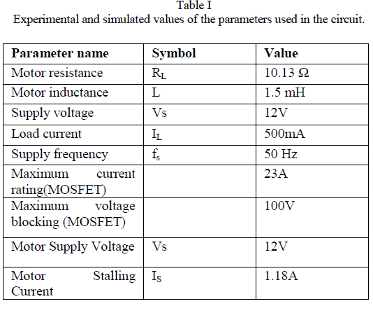
CIRCUIT PARAMETERS |
 |
| In case of inductive load, the current is not in phase with the voltage waveform at the load side which leads to poor supply power factor and high low order harmonic content at both supply and load side especially for large firing angles [13]. In symmetrical angle method the circuit is turned ON at ωt=(π-β)/2 and turned off at ωt=(π+β)/2. So circuit remains ON for β.The fundamental component of input current is in phase with input voltage, and as a result the displacement factor is unity (1.0). |
| In this paper, a brief description about the load is given, a DC motor, followed by the various practical observations and theoretical calculations for the circuit. The operation of this controlled rectifier as variable voltage source employing SAC and EAC is evaluated and compared with PAC from power factor improvement point of view. The MATLAB based simulation results are verified experimentally. |
CIRCUIT DESCRIPTION AND WORKING |
A. Symmetrical angle control |
| The output of the triggering circuit is a square wave which is used to trigger a MOSFET, so that it remains in the turned on state for the period ωt= (π-β)/2 to ωt= (π+β)/2. The MOSFET conducts when the trigger pulse is high and is turned off when the pulse is low. So a square wave which remains high for a period ωt= (π- to ωt= (π+β)/2 is generated to trigger the MOSFET. |
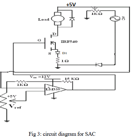 |
| Fig 3 shows the circuit diagram where the MOSFET is turned ON when the comparator output is positive and turned OFF when the comparator output is negative. In the ON state, the current flows through the load and we get an output as shown in the fig 2. Thus we get a half wave controlled rectifier using symmetric angle control method. The angle can be controlled by adjusting the Vref by changing the value of the potentiometer. |
B. Extinction Angle Control |
| Two methods have been used for designing the controlled rectifier using EAC: |
| i) Using AND logic, and |
| ii) Using MMV. |
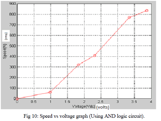
| i) Circuit using AND Logic: This method consists of a triggering circuit which outputs a square wave which is used to trigger a MOSFET, so that it remains in the turned on state for the period ωt=0 to ωt=(π−β)=α. The MOSFET conducts when the trigger pulse is high and turns off when the pulse is low. So a square wave which remains high for a period ωt=0 to ωt= (π−β) =α is generated to trigger the MOSFET. |
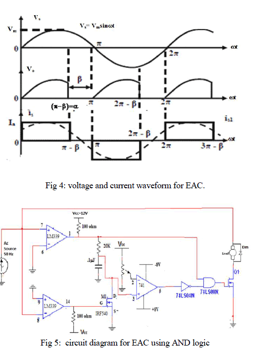 |
| As, shown in fig 5, a 15V, AC voltage is compared with a reference voltage Vref (GND) to form a zero cross detector and produces a square wave output. When the output of the comparator is positive, the capacitor is charged. Another square wave output is generated by reversing the polarity of the comparator inputs. This square wave triggers the MOSFET, M1 which gives a path for the capacitor to discharge through it. |
| During the positive half cycle of the square wave the capacitor gradually charges up to Vs. |
| Vc= Vs(1-e-t/RC) ------------ (1) |
| Where, Vs=5V, Vc is the voltage in the capacitor and RC is the time constant. |
| The capacitor voltage is compared with a reference voltage and its output along with the output of the first comparison is fed to an AND gate. The AND gate output is then provided as the triggering pulse to the MOSFET, M2 and the load (motor) is connected to the drain and the AC supply as shown in fig 5. |
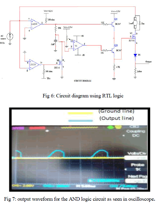
| Due to mismatch of logic level voltages, the AND gate is implemented using resistor transistors logic (RTL) (shown in Fig 6). |
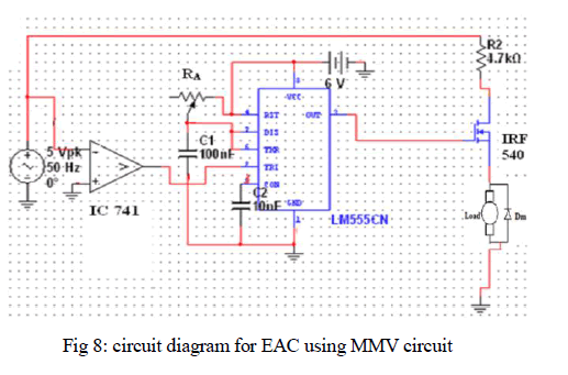
| The modified circuit diagram is shown in Fig 6. For a waveform to be HIGH for a time period of 8ms, the reference voltage can be calculated as 4.908 V using equation (1). |
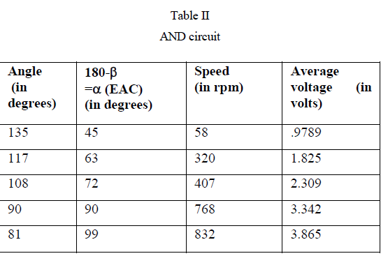
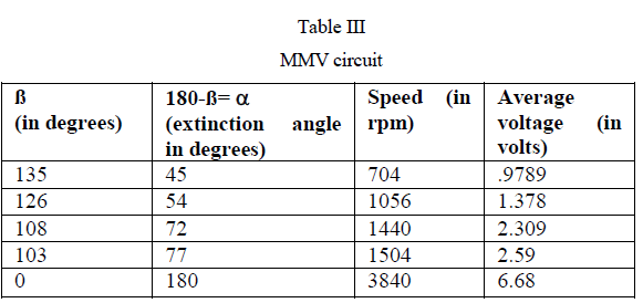
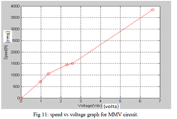
| ii) Circuit Using MMV: This circuit also contains a triggering circuit like the previous circuit. Here a monostable multivibrator (MMV) is used to generate the square wave for triggering the MOSFET. |
 |
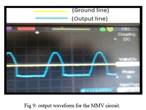
| The MMV is made using a 555 timer as shown in the fig 8 and its output waveform is shown in fig 9. The pulse begins when the 555 timer receives a signal at the trigger input that falls below a third of the voltage supply. The width of the output pulse is determined by the time constant of an RC network, which consists of a capacitor (C) and a resistor (R). The output pulse ends when the voltage on the capacitor equals 2/3 of the supply voltage. The output pulse width can be varied as per requirement. |
| The output pulse width of time t, which is the time it takes to charge C to 2/3 of the supply voltage, is given by |
| t= RCln(3) ≈ 1.1RC -----------equation (2) |
| where t is in seconds, R is in ohms and C is in farads. |
| The output pulse generated by the timer is used to trigger the MOSFET to obtain the extinction angle control waveform. So, 0 < RA < 90kΩ. |
 |
 |
 |
| An electrolytic capacitor can be connected across the load to reduce noise. The rating of the capacitor used is 25V and the minimum required rating is 24V as the capacitor charges to 2Vs, where Vs is the supplied voltage which is equal to the 12V. |
 |
 |
 |
COMPARISON OF POWER FACTORS |
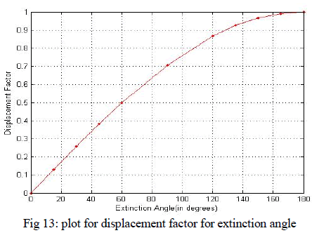
| For firing and symmetric angle controlled rectifiers, is the angle at which conduction starts and for extinction angle controlled rectifiers, is the angle at which conduction stops. is the period for which the circuit conducts. |
 |
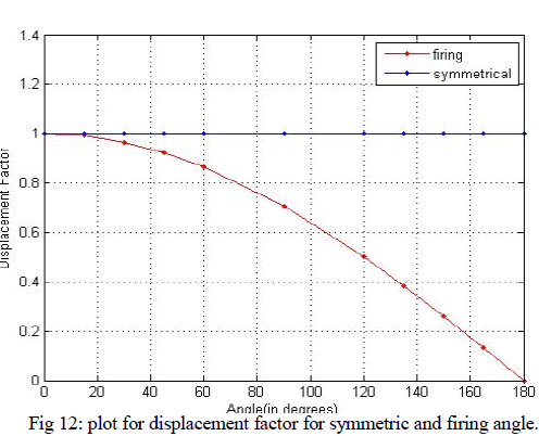 |
| In symmetrical angle, the plot is a straight line as the displacement factor is unity for all angles whereas in firing angle, it decreases as the firing angle increases. |
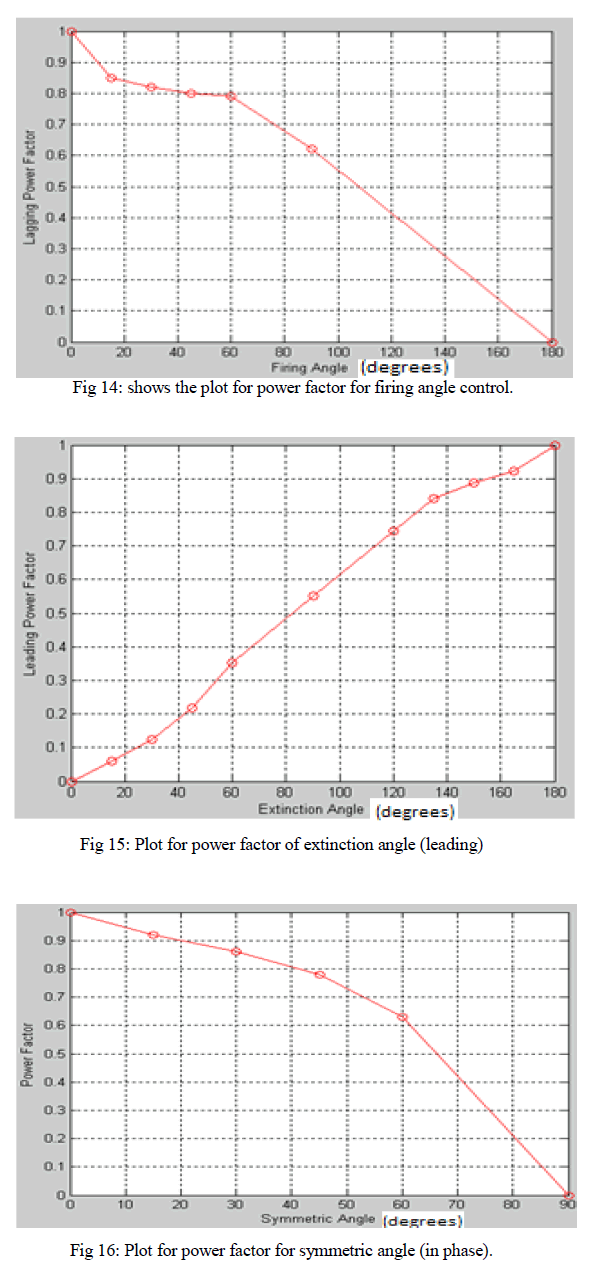
| Fig 15 shows the variation of the supply power factor versus the extinction angle over the complete range of control for inductive load condition. As the angle at which the circuit commutates (α) increases the power factor increases. In extinction angle control, the power factor is leading. |
| In symmetric angle control, the power factor decreases as the angle at which the circuit is fired increases. |
 |
HARMONIC ANALYSIS |
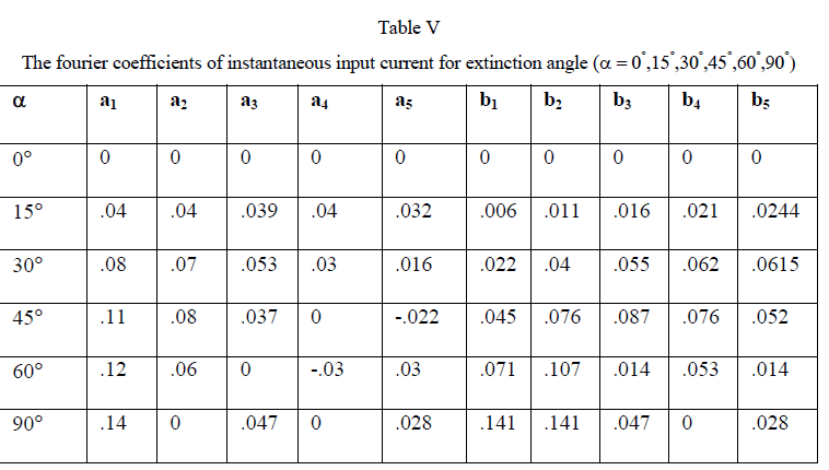
| Angle is the angle at which the conduction stops for an extinction angle controlled rectifier. Table V shows EAC has better THD of load current than PAC because of the continuous load current for inductive load circuit. |
CONCLUSION |
| After calculating the power factors and plotting the graphs for firing angle, symmetrical angle and extinction controlled methods and comparing them we can conclude that the power factor leads in extinction angle while it lags in firing angle. Inductive loads consume reactive power with current waveform lagging the voltage. Capacitive loads generate reactive power with current leading the voltage. In order to compensate the lag in current compared to the voltage in case of an inductive load, the extinction angle will imitate the capacitive load. The value of power factor in case of symmetrical angle becomes 0 at 90ïÃâð. Also, the voltage and current waveforms in symmetrical angle are in phase with each other which results in the value of displacement factor equal to become one at all the angles. |
 |
 |
| The paper presents the EAC technique for single-phased dc-dc control rectifiers. The EAC technique provides a considerable improvement in the input power factor. This improvement is mainly due to the improvement in the displacement factor. The control rectifier has been applied to a static dc motor. A good agreement is obtained between the simulated and the experimental results. |
References |
|