ISSN ONLINE(2278-8875) PRINT (2320-3765)
ISSN ONLINE(2278-8875) PRINT (2320-3765)
Neena Mani1, Sudheesh T.P2, Vinu Joseph3,Titto V.D4, Shamnas P.S5
|
| Related article at Pubmed, Scholar Google |
Visit for more related articles at International Journal of Advanced Research in Electrical, Electronics and Instrumentation Engineering
Water level indicator is widely used in many industries and houses .In this paper a programmed microcontroller is the basic component for the water level indicator. ATmega 32A microcontroller is helps to indicate the level of water or any other conducting liquid. With the help of an lcd display we can see all the level of the water contained in a tank or in any other vessels. A liquid level sensor (transistor circuit) detects the present level of the liquid in the tank in terms of the voltage across transistor and feeds it to the microcontroller and the microcontroller generates a corresponding output text which in then displayed in the LCD. If the water level is full, then the circuits beeps through the buzzer notifying that the water level is full.
Keywords |
| ATmega 32AMicrocontroller, LCD |
INTRODUCTION |
| Measurement of the height of water in a tank or a big structure such as dam is a major subject of study in engineering. It is not easy to measure the water level in large architectural structures physically. Hence we always have the necessity of a electronic equipment that can measure the water level in a container and show a message informing about the water level in it. Sustainability of available water resource in many reason of the word is now a dominant issue. This problem is quietly related to poor water allocation, inefficient use, and lack of adequate and integrated water management. Water is commonly used for agriculture, industry, and domestic consumption. Therefore, efficient use and water monitoring are potential constraint for home or office water management system. Last few decades several monitoring system integrated with water level detection have become accepted. Measuring water level is an essential task for government and residence perspective. In this way, it would be possible to track the actual implementation of such initiatives with integration of various additional controlling activities. Therefore, water level indicating system implementation makes potential significance in home applications. Such an indicator is used in tanks to indicate the level of liquids and alert us when the tank is full. So by this circuit we can monitor the various levels of the tank and can avoid spillage of water and also we can configure our supplies according to the various levels of tank. Such module or circuit can be installed in big buildings where manual monitor of tanks is difficult and its indicator can be placed at some centralized place. This device is build on a microcontroller – ATmega32, readings are displayed using a 16x2 LCD and water level limit is notified by a noise of the buzzer. This circuit works on the principle that water conducts electricity. A wire connected to VCC and four other wires are dipped in tank at different levels namely quarter, half, three-fourth, full and their output are taken to different ports of the microcontroller via a transistor BC547. Other pins from the microcontroller are connected to data pins like RS, RW, and EN pins of LCD. Initially when the tank is empty LCD will show the message VACANT. As the tank starts filling up wire at different levels get some positive voltage, due to conducting nature of water. This voltage is then fed to their corresponding pins on controller. When level reaches to quarter level, LCD displays the message QUARTER. On further rise of level, HALF and QUARTER is displayed on LCD. When tank gets full LCD shows the message FULL. A buzzer is also provided to produce a alert the user when the tank gets filled. This buzzer can be made off by pressing the switch connected between pin 15 of controller and VCC. |
WATER LEVEL INDICATOR USING ATMEGA 32A |
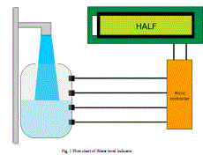
| Fig .1 shows the simple flow chart of water level indicator which indicates which indicates four levels of water ATMEGA32 microcontroller was chosen as it has many benefits in comparison to other microcontrollers. Its features and benefits over other microprocessors are as follows. |
| 1. High-performance |
| 2. Low-power AVR 8-bit Microcontroller |
| 3. Advanced RISC (reduced instruction set computer) Architecture |
| 4. High Endurance Non-volatile Memory segment |
 |
| Fig .1 Flow chart of Water level indicator |
| Other main components used are transistors,buzzer and an lcd display.Transistors are connected to the input ports of the microcontroller where it will act as switches to display each level in the lcd display .Fig .2 shows the BC 547 transistor and the buzzer. |
 |
A. BC547 transistor |
| A BC547 transistor is a negative-positive-negative (NPN) transistor that is used for many purposes. Together with other electronic components, such as resistors, coils, and capacitors, it can be used as the active component for switches and amplifiers. Like all other NPN transistors, this type has an emitter terminal, a base or control terminal, and a collector terminal. In a typical configuration, the current flowing from the base to the emitter controls the collector current. A short vertical line, which is the base, can indicate the transistor schematic for an NPN transistor, and the emitter, which is a diagonal line connecting to the base, is an arrowhead pointing away from the base. |
B. Buzzer |
| A buzzer or beeper is a signaling device, usually electronic, typically used in automobiles, household appliances such as a microwave oven, or game shows. The word “buzzer” comes from the rasping noise that buzzers made when they were electromechanical devices, operated from stepped-down AC line voltage at 50 or 60 cycles. Other sounds commonly used to indicate that a button has been pressed are a ring or a beep.It most commonly consists of a number of switches or sensors connected to a control unit that determines if and which button was pushed or a preset time has lapsed, and usually illuminates a light on the appropriate button or control panel, and sounds a warning in the form of a continuous or intermittent buzzing or beeping sound. Initially this device was based on an electromechanical system which was identical to an electric bell without the metal gong (which makes the ringing noise). |
| Often these units were anchored to a wall or ceiling and used the ceiling or wall as a sounding board. Another implementation with some AC-connected devic.es was to implement a circuit to make the AC current into a noise loud enough to drive a loudspeaker and hook this circuit up to a cheap 8-ohm speaker. Nowadays, it is more popular to use a ceramic-based piezoelectric sounder like a Sonalert which makes a high-pitched tone. Usually these were hooked up to “driver” circuits which varied the pitch of the sound or pulsed the sound on and off. |
C. 16*2 LCD display |
| LCD (Liquid Crystal Display) screen is an electronic display module and find a wide range of applications. A 16x2 LCD is very basic module and is very commonly used in various devices and circuits. These modules are preferred over seven segments and other multi segment LEDs. The reasons being |
| 1. LCDs are economical |
| 2. Ease of programming for characters and graphics. |
| 3. The ability to display unlimited numbers, special and even custom characters (unlike in seven segments), graphics and so on |
| A 16x2 LCD means it can display 16 characters per line and there are 2 such lines. In this LCD each character is displayed in 5x7 pixel matrix. This LCD has two registers, namely, Command and Data. The command register stores the command instructions given to the LCD. A command is an instruction given to LCD to do a predefined task like initializing it, clearing its screen, setting the cursor position, controlling display etc. The data register stores the data to be displayed on the LCD. The data is the ASCII value of the character to be displayed on the LCD. |
CIRCUIT DIAGRAMS AND OPERATION |
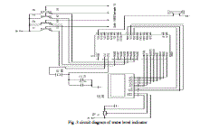
| One of the major advantages of this system is its simple circuit and working principle. The circuit is divided into two parts. First one is the microcontroller section which is kept on the breadboard and second is the transmitter section and its base is kept inside the water tank. Both of them are discussed in detail in coming sections.The bases of each of the four NPN transistors are dipped in the water tank at various levels. Each level corresponds to quarter, half, three quarters and the full height of the tank respectively. |
| The collector terminals of each of these transistors are connected to a +5 volt level. The emitter terminals are connected to input pins of PORT A of the microcontroller. The microcontroller continuously monitors the state of each of these input pins. If not even a single one of them is high, the controller indicates the user that the tank is empty by displaying appropriate string through the LCD. If the first pin, which is the one corresponding to the quarter level of the tank is high then LCD displays “quarter”. If both the first and second pins are high, then LCD displays “half full”. Similarly if the first three pins are high then we infer from the LCD that the water level is three quarters of the tank. Likewise a high on all four pins displays the message “full”. Once the water tank is full, the buzzer produces a short audible sound warning the user to switch off the motor. |
 |
| Fig .3 circuit diagram of water level indicator |
 |
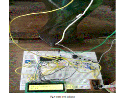
| Fig.4 water level indicator |
CONCLUSION |
| Water level indicator is a promising application made by the use of microcontroller. It can be used in some other conducting liquid also for finding the levels of that liquid |
References |
|