ISSN ONLINE(2278-8875) PRINT (2320-3765)
ISSN ONLINE(2278-8875) PRINT (2320-3765)
Geetha B1, Rohin Reji Paul2, Nimisha K K3, Rosily Antony4, Varun Jo Abu5
|
| Related article at Pubmed, Scholar Google |
Visit for more related articles at International Journal of Advanced Research in Electrical, Electronics and Instrumentation Engineering
This project aims to obtain the energy meter reading and display the reading obtained in LCD. As a result the tedious job of collecting the meter reading manually is avoided. An added feature is to display the cost that the consumer has to pay using a display system. Thus we are trying to provide a cost effective and easy to implement solution for collecting the energy meter reading.
Keywords |
| Energy-meter, ATMEGA16 microcontroller, 555 Timer, LDR |
INTRODUCTION |
| Usually Energy meters are used to get the amount of electrical energy consumed in the given period of time. It gives just the number of units consumed in KWh and not the cost. |
| Smart Energy Meter can take readings from the energy meter and is used for calculating the cost. This system works with an ATmega16A microcontroller. The count obtained from the Watt-hour meter is stored in the registers of the microcontroller.. An added feature is to display the cost that the consumer has to pay using a display system. Thus we are trying to provide a cost effective and easy to implement solution for collecting the energy meter reading. |
| The value is displayed on the LCD display. A push button switch is provided which will refresh and update the values which includes both number of units and cost. |
WORKING AND CIRCUIT OPERATION |
A. Watt-hour meter Simulation Using 555 timer |
| The 555 timer is a highly stable device for generating accurate time delays or oscillations. 555 is an eight pin DIP IC. In this system, 555 is used as an astable multivibrator with a varying pulse width. The 555 can be used with a supply voltage in the range of 5v-18v and can drive the load up to 200mA. It is compatible with both TTL and CMOS logic circuits. Because of wide range of supply voltage the 555 timer is versatile and easy to use. 555 can provide a delay varying from microseconds to hours. 555 to be work as astable pins 6 and 2 should be shorted. Each output pulse of the 555 is taken as a unit and is stored in microcontroller. |
| DESIGN |
| T=0.69(Ra+Rb) |
| Select C=10 uF, |
| Ra=10000 ohm |
| And select Rb a pot of 10 K ohm so that time period can be varied. So a wide range of pulse width is obtained through this design. |
B. Circuit Operation |
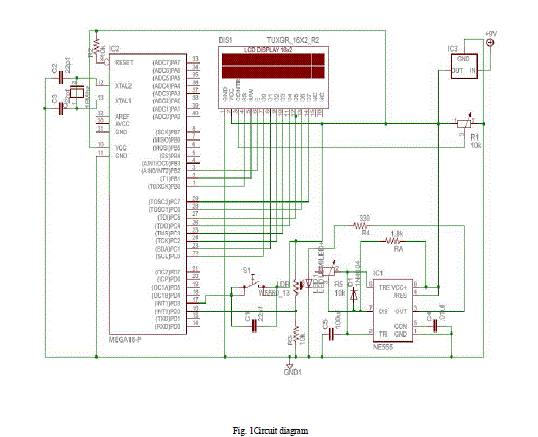
| The 555 timer produces square wave with 50 percent duty cycle. The frequency is varied by varying the resistance Rb. This is given to the LED. An LDR is connected to the 5V supply and is grounded through 10k resistance. When the LED glows the resistance of the LDR decreases and most of the voltage drop is formed across the 10k resistance. This voltage is given to the interrupt pin of ATmega 16A. |
 |
| Fig. 1Circuit diagram |
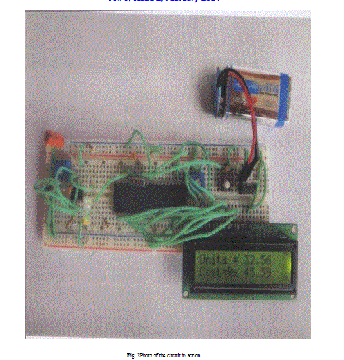
| The microcontroller ATmega16 is programmed such that each time the voltage in the pin of microcontroller changes from zero to a high value the count is incremented. The cost of the unit consumed is found by using the formula used by KSEB. The cost along with the number of units is displayed through an lcd when a rising edge trigger is applied to another external interrupt pin (INT1) which is internally pulled down. A debouncing capacitor is placed across the push button. |
 |
| Fig. 2Photo of the circuit in action |
CONCLUSION |
| The project was developed for reading the energy meter and display the unit consumed and cost. The project if implemented would reduce the tedious and time consuming job of taking the energy meter reading manually. The system can be even upgraded with added facilities like mobile banking, user’s displays etc. |
| Also implementation of this system could save large amount of money to the power companies which they spend to collect the meter reading manually |
References |
|