ISSN ONLINE(2278-8875) PRINT (2320-3765)
ISSN ONLINE(2278-8875) PRINT (2320-3765)
P.Aswini1, Mrs. K.S.Pavithra2
|
| Related article at Pubmed, Scholar Google |
Visit for more related articles at International Journal of Advanced Research in Electrical, Electronics and Instrumentation Engineering
This paper presents a high reliability and high efficiency light-emitting diodes for low power application. An AC-DC converter is a common converter topology approach for low voltage application. The prefect option for this approach is a Asymmetrical Half Bridge converter it has high efficiency constant switching frequency operation and small output filter. Asymmetrical Half Bridge is a perfect candidate for SD-SR because the transformer do not have dead times. Another main issue is its closed-loop controller does not be very fast, it will also cancel the previously shown low frequency ripple. A technique used to reduce the output voltage ripple is feed forward technique. The proposed method is an average current mode control technique gives low frequency ripple in the output voltage. Also a related problem to the AHB is overcome by proposed technique. The results obtained with a 60w topology gives efficiency of AHB as 94%. Index Terms- AC-DC converter, asymmetrical half bridge (AHB), self-driven synchronous rectification (SD-SR), LED drivers
Index Terms |
| AC-DC converter, asymmetrical half bridge (AHB), self-driven synchronous rectification (SD-SR), LED drivers |
INTRODUCTION |
| Electric Lighting is an essential part of our lives, and is a major component in energy consumption. The types of lighting devices commonly adopted for electric lighting is the incandescent lamps, the gas-discharge lamps and solid state lighting devices. There are various dimming techniques introduced for different types of lighting devices. For incandescent lamps, dimming is typically performed by controlling the firing angle of a thyristor. For Gas discharge lamps, dimming technique revolve around the control of voltage level, duty cycle and frequency. For solid-state lighting devices, the dimming technique is to vary the dc level of the forward current [1]. |
| Due to the high efficiency of LEDs, it is getting more and more attractive in the world, particularly for industrial applications. The high efficiency LED system needs the high-efficiency power supply to feed the LED [3]. LEDs are very attractive lighting sources due to their excellent characteristics. Many types of power switching converter used to adapt primary energy sources to the requirements [5]. HB LEDs have been widely accepted because of superior longevity, Low-maintenance requirements and improve luminance. For an LED load, a small variation in driving voltage leads to large variation in the LED current. LED current with large ripple will lead to seriously affect the reliability and longevity [6]. |
| With the enormous progress recently achieved in solid state lighting technology were the LEDs are now approaching the luminous performance level. LEDs are mercury-free and can be safely disposed or recycled at the end of life. LEDs are being increasingly used in different illumination applications; the necessity of an efficient driver with optimized control circuit becomes more important. Since LEDs is current driven devices in which light produced and the recombination of injected holes and electrons in a semiconductor junction, luminous intensity of LEDs are typically controlled by controlling the forward current only in one direction, another method for driving LEDs is using a constant dc [8]. |
| In this paper, the AHB is designed for low voltage high current application. Also this paper deals with average current mode control. Average current mode control is typically a two loop control method with inner current loop and outer voltage loop. ACMC is a current control technique that has an almost constant frequency and produces a user-defined current waveform. |
 |
AHB |
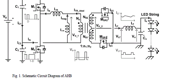
| Asymmetric Half bridge converter has drawn attention due to its simplicity and inherent zero voltage switching capability. This converter has several advantages low MOSFET voltage and current stress, small output capacitor and inductor, minimum component count, and simple control. The schematic circuit diagram of the AHB is shown in fig. 1. It consists of an HB converter with their switches controlled with complementary signals [14]. This complementary driving signals implies that the voltage of the input capacitors are not necessarily equal |
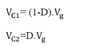 |
| Where VC1 and VC2 are the voltages across the input capacitor C1 and C2, D is the duty cycle and Vg is the input voltage of the AHB. |
| The second important aspect regarding the AHB is the switching losses in MOSFETs and diodes. The switching losses of the MOSFETs can be reduced by employing the techniques that allow them to reach zero-voltage switching (ZVS). ZVS is quite difficult to achieve in the AHB because the amount of energy stored in the leakage inductance is not high enough. The asymmetric converter control was proposed to achieve ZVS operation for halfbridge switches. Two drive signals are complementarily generated and applied to high-side and low-side switches respectively. The two HB switches may be turned on at ZVS conditions, attributing to the fact that the transformer primary current charges and discharges the junction capacitance. However, asymmetric stress distribution on the corresponding components may occur due to the asymmetric duty cycle distribution for the two primary switches. In other words, voltage and current stresses on the switches including both the primary side and secondary side MOSFETs are not identical. As a result, diodes or synchronous rectifiers with higher voltage rating are needed at the penalty of degrading the performance and efficiency of the rectifier stage. |
 |
 |
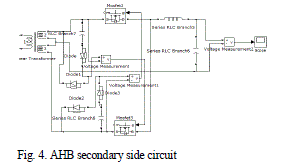
| The secondary side of the AHB is the Self Driven Synchronous Rectification. The self-driven drive scheme is the simplest synchronous rectifier drive scheme. In the self-driven technique, the voltage across the transformer secondary is used to drive the gates of the synchronous rectifiers is shown in fig 4. Separate windings on the secondary side of the transformer can be used to drive the forward synchronous rectifier and the freewheeling synchronous rectifier. This is usually done to allow a different turn’s ratio from the primary winding to the gate drive windings, allowing synchronous rectification to be used for higher or lower output voltages. A synchronous rectifier is a circuit that emulates a diode, allowing current to pass in one direction but not the other without the losses associated with junction or Schottky devices. The circuit comprises a pass-element (most often a power MOSFET), a sense element, a sense-signal conditioner, and a driver. There are two broad techniques to implement the synchronous rectifier function. The first derives a sync signal from the primary controller. But this method often requires the control signal to cross a galvanic barrier, which can be costly, consume a large board area, and limit the converter’s upper frequency limit. |
 |
| The second method derives the control signal independently by sensing the electrical conditions at the pass element. In the off state, the sense element detects the polarity of the voltage applied to the pass element. The signal conditioner amplifies the sense signal and determines the polarity of the sensed voltage. When the applied voltage is of the correct polarity for forward conduction, the signal conditioner turns on the driver, which provides the necessary signal to operate the pass element. SR improves efficiency, thermal performance, power density, manufacturability, and reliability, and decreases the overall system cost of power supply systems. The two MOSFETs must be driven in a complimentary manner with a small dead time between their conduction intervals to avoid shoot–through. The synchronous FET operates in the third quadrant, because the current flows from the source to the drain [16]. |
| The advantages of using SR in high-performance, highpower converters include better efficiency, lower power dissipation, better thermal performance, lower profile, increased quality, improved manufacturing yields though automated assembly processes (higher reliability), and inherently optimal current sharing when synchronous FETs are paralleled. As mentioned above, a number of MOSFETs can be paralleled to handle higher output currents. Self Driven – Synchronous Rectification is the simplest one as the driving signals of the synchronous rectification MOSFETs are obtained from the secondary winding of the transformer. Therefore, no additional controllers are necessary and no problems with programmed delays will appear. Nevertheless, the SDSR is a more desirable approach when the peak value of the voltage across the secondary winding does not change when the output voltage is modified. If the voltage across the secondary winding does not change with the output voltage variations, the driving circuit can be easily designed in order to assure that the driving signals of the SR MOSFETs are inside the acceptable voltage limits. |
| For a low-voltage high-current application synchronous rectification is mandatory in order to achieve high efficiency. SD-SR is simplest as the driving signals of the SR MOSFETs are obtained from the secondary winding of the transformer. |
AVERAGE CURRENT MODE CONTROL TECHNIQUE |
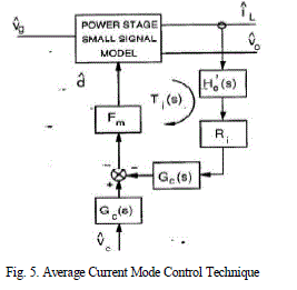
| Average current mode control differs from peak current mode control in that it attempts to control the average value of the current to follow a reference as opposed to controlling the switch peak current. The Average Current Mode Control (ACMC) is typically a two loop control method (inner loop, current; outer loop, voltage) for power electronic converters. Advantages of ACMC include large noise margin, no requirement for additional slope compensation, easy current limit implementation, excellent voltage and current regulation, simple compensation, good behavior in both continuous and discontinuous inductor current modes, and has inherent Vin and Vout feed-forward properties. ACMC is a current control technique that has an almost constant frequency and produces a user-defined current waveform. It has a fast response time and is capable of supporting a wide range of power circuit topologies. |
| ACMC is based on a compensator circuit which compensates the poles of an integrating filter transfer function. A wide range of power conversion applications use the current control technique. This technique controls the peak inductor current to regulate the converter output. For converters with relatively high output currents (5A to 25A), lowering the value of the currentsense resistor in current-mode control (CMC) techniques helps boost efficiency. In this article, CMC implies constant-frequency with peak current-sensing. |
 |
DESIGN PROCEDURE |
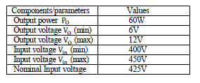
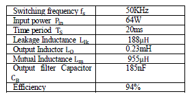
| In this section, a design procedure is presented using the fig.1 as a reference. A centre tapped transformer is used in the rectifier stage. A AC-DC converter with a 60W/12V output has been selected as a design example. The AHB with Average Current Mode Control gives low voltage, high current with corresponding high efficiency. |
| The design specifications are as follows: |
| TABLE I |
| Components and Parameter Values |
 |
 |
| The input power of the AHB is given as: |
 |
| The power conversion efficiency must be estimated to calculate the maximum input power with a given maximum output power. The efficiency is given as: |
 |
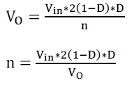
| To determine the transformer turns ratio with the corresponding output voltage as |
 |
| By choosing the duty cycle losses as 10% of the switching cycle, the leakage inductance is obtained as: |
 |
| The output ripple inductor is given by choosing the current ripple as 20% |
 |
| The magnetizing inductance value is closely related to the ZVS condition, since it determines the peak current level during the switching transition. |
 |
| To find output filter capacitor value: |
 |
| The maximum capacitor voltage is theoretically half of the input voltage. However, it can reach the input voltage while the converter is not operating if the leakage currents of the MOSFETs are unbalanced. Thus, voltage rating should be higher than maximum input voltage. |
SIMULATION RESULTS |
| MATLAB simulation software is widely used in Industries to model and simulates different electrical and electronic equipments. The simulation part of this paper is done by the help of SimPowerSystem and Simulink packages. It offers a powerful programming language, excellent graphics, and a wide range of expert knowledge. MATLAB is published by and a trademark of The Math Works, Inc. the focus in MATLAB is on computation, not mathematics: Symbolic expressions and manipulations are not possible (except through the optional Symbolic Toolbox, a clever interface to maple). All results are not only numerical but inexact, thanks to the rounding errors inherent in computer arithmetic. The limitation to numerical computation can be seen as a drawback, but it’s a source of strength too: MATLAB is much preferred to Maple, Mathematical, and the like when it comes to numeric. On the other hand, compared to other numerically oriented languages like C++ and FORTAN, MATLAB is much easier to use and comes with a huge standard library. The unfavorable comparison here is a gap in execution speed. This gap is not always as dramatic as popular has it can often be narrowed or closed with good MATLAB programming. Moreover, one can link other codes into MATLAB, or vice versa, and MATLAB now optionally supports parallel computing. Still, MATLAB is usually not the tool of choice for maximum-performance computing. The MATLAB niche is numerical computation on workstations for non-experts in computation. This is a huge niche one way to tell is to look at the number of MATLAB-related books on mathworks.com. Even for supercomputer users, MATLAB can be a valuable environment in which to explore and fine-tune algorithms before more laborious coding in another language. Most successful computing languages and environments acquire a distinctive character or culture. |
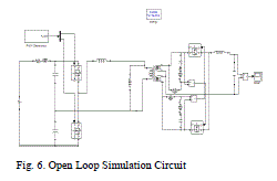 |
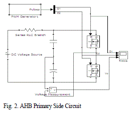
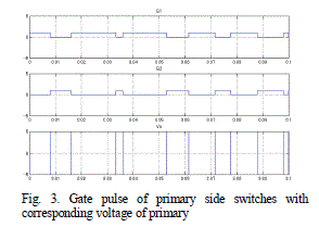
| The open loop asymmetrical half-bridge converter simulation diagram is shown above. Its main feature is that primary switches are driven with complementary signals and, consequently, one of them is always turned on. As the volt-second balance in the magnetizing inductance has to be maintained, these complementary driving signals imply that the voltages of the input capacitors are not necessarily equal. In this simulation diagram, self driven-synchronous rectification is used in the secondary side. |
 |
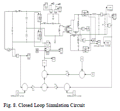 |
| The above simulation diagram shows for the proposed average current mode control method which gives both voltage and current in the closed loop circuit. Average current mode control differs from peak current mode control in that it attempts to control the average value of the current to follow a reference as opposed to controlling the switch peak current. Average current mode control has better noise immunity compared with peak current control. This is due to a higher current amplifier gain employed in average current controllers. |
 |
 |
| TABLE II |
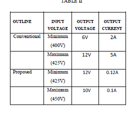 |
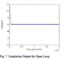
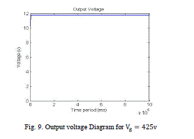
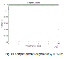
| The performance of open loop circuit is compared with that of conventional closed loop. Output ripples in conventional closed loop has reduced considerably. Simulation for the proposed circuit is done for various input voltage. The output voltage is maintained at a constant value of 12V for a input voltage range of 425V to 450V. The proposed circuit was simulated for different voltages. |
CONCLUSION |
| In this dissertation, AHB topology of on-board AC-DC converter for LED drivers is studied and its control technique here explored focusing on two main aspectsthe efficiency and the low frequency ripple of the output voltage, which are two key requirements for on-board AC-DC converters. The main points are summarized as below. This work focuses on the half-bridge converter due to its popularity, simplicity and adaptability for lowvoltage high-current applications. First, the half-bridge converter requires only two MOSFETs, which is only half of the number used in full-bridge topology. This helps to reduce the cost for practical applications. LEDs are slow loads, it is possible to design a feed-forward loop optimized for cancelling this low-frequency ripple, while the closed-loop control assures stability and output voltage regulation due to variations in the characteristics of the LEDs, which are determined by their warming-up. This AHB gives efficiency as 94.5%. For low voltage high current application this gives 12V voltage and 5A current for the corresponding input voltage. |
References |
|