ISSN ONLINE(2278-8875) PRINT (2320-3765)
ISSN ONLINE(2278-8875) PRINT (2320-3765)
Pankaj Sagar1, Likhin M.2, Abdul Nazer K. H.3, Naveen N.4, Asha Joseph4
|
| Related article at Pubmed, Scholar Google |
Visit for more related articles at International Journal of Advanced Research in Electrical, Electronics and Instrumentation Engineering
With the development of embedded Real Time Operating System (RTOS), dedicated controllers normally used to control single process loops are being replaced by shared controllers which are ported with RTOS running multiple control algorithms parallelly. This work demonstrates a Cerebral Model Neural Network (CMNN) based control algorithm as a real time application in MPC8260 (PowerPC) embedded processor with VxWorks RTOS. Process signals from the sensors are interfaced to MPC8260 board through serial port and control signals given to the actuator are displayed on a client system running Hyper-Terminal application
Keywords |
| VxWorks, RTOS, PowerPC, MPC8260 |
I. INTRODUCTION |
| An important capability of an intelligent system is the ability to improve its future performance based on the experience within its environment. the concept of learning is usually used to describe the process by which this capability is achieved [1]. The control system can be viewed as a mapping from plant outputs to actuation commands so as to achieve certain control objectives,with learning as the process of modifying this mapping to improve future closed-looped system performance. The information required for learning, that is , the information that is required to correctly generate the desired control system mapping,is obtained through direct interaction with the plant( and its environment). Thus learning can be used to compensate for the lack of priori design information by exploiting empirical information that is gained experimentally [2]. |
II. VXWORKS AND POWERPC |
| A. VxWorks |
| VxWorks is a real-time operating system developed by Wind River Systems of Alameda, California, USA in 1987. VxWorks has been ported to a number of platforms and now runs on practically any modern CPU that is used in the embedded market. This includes the x86 families, MIPS, PowerPC, Free scale, Cold Fire, Intel i960, SH-4 and the closely related family of ARM, Strong ARM and xScale. |
| One key to VxWorkss effective relationship with host development machines is its extensive networking facilities. By providing a fast, easy-to-use connection between the target and host systems, the network allows full use of the host machine as a development system, as a debugging host, and as a provider of non real-time services in a final system. VxWorks operates at frequencies of 66MHz, 200MHz, and 300MHz [3]. |
| At the heart of the VxWorks, run-time system lies the highly efficient wind micro kernel, which supports a full range of real-time features including fast multitasking, interrupt support, and both pre-emptive and round-robin scheduling. The modular run-time system is fully scalable, allowing the user to configure VxWorks for the widest range of applications from minimal embedded systems to the most complex distributed designs. In VxWorks the main entity is the task. The tasks in VxWorks share memory. In this respect they are similar to threads. It supports a maximum of 256 priority levels. VxWorks has a number of inter task communication mechanisms shared memory, semaphores, mutexes and message queues. The mutex semaphore in VxWorks supports the priority-inheritance algorithm [4]. |
| B. Tornado Development Environment |
| Wind River has an integrated development environment for embedded applications called Tornado. Tornado is a completely open environment designed to be customized and extended by the developer. Tornado is an Integrated development environment (IDE) for software cross-development targeting VxWorks 5.x. VxWorks is the dedicated RTOS running on the target, while Tornado, the complete development environment is running on the host. Tornado2.2 is supported for the following target architectures such as PowerPC, Pentium, Arm, MIPS, SuperH, Cold Fire, and VxSim. Here we are using the PowerPC target [5]. Tornado consists of the following elements; |
| VxWorks 5.x target operating system |
| Application Building (Cross-compiler and associated programs) |
| An integrated development environment (IDE) that facilitates managing and building projects, establishing hosttarge communication, and running, debugging and monitoring VxWorks applications |
| VxSim simulator |
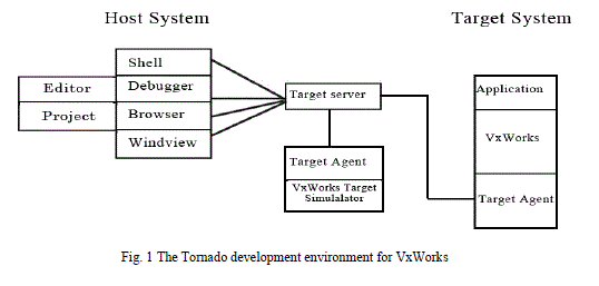 |
| The Fig.1 illustrates the relationship between thecomponents of tornado and host system. The application isdeveloped on host machine. After successful compilation onhost, the application can be downloaded to the target andexecuted on the target. The tornado PC is a normal PC thatruns the tornado tools, and the target CPU is a single boardcomputer (target) where Vxworks is to run. |
| C. PowerPC |
| YourPowerPC (Performance Optimization with Enhanced RISC Performance Computing) is a RISC architecture created by the 1991, AIM. Networking is area where embedded PowerPC processors are found in large numbers. In our target, we are using Motorola Power PC8260 (MPC8260).The MPC8260 Power QUICC II is a versatile communications processor that integrates on one chip a high performance PowerPC RISC microprocessor, a very flexible system integration unit, and many communications peripheral controllers that can be used in a variety of applications, particularly in communications and networking systems [6]. |
| The basics components of MPC8260 include |
| MPC603e Core |
| System Interface Unit (SIU)VxSim simulator |
| Communications Processor Module (CPM) |
| The MPC603e core is derived from the PowerPC MPC603e microprocessor without the floating-point unit and with power management modifications. The core is a high performance low-power implementation of the PowerPC family of reduced instruction set portion of the PowerPC architecture, which provides 32-bit effective addresses, integer data types of 8, 16, and 32 bits. The MPC603e cache provides snooping to ensure data coherency with other masters. This helps ensure coherency between the CPM and system core. It has a 64- bit split transaction external data bus, which is connected directly to the external MPC8260 pins. |
| The MPC603e core has an internal common on-chip (COP) debug processor. This processor allows access to internal scan chains for debugging purposes. It is also used as a serial connection to the core for emulator support. The System interface unit (SIU) consists of a 60X compatible parallel system bus configurable to 64 bit data width, and an memory controller supporting 12 memory banks that can be allocated for either the system or the local bus. The SIU supports |
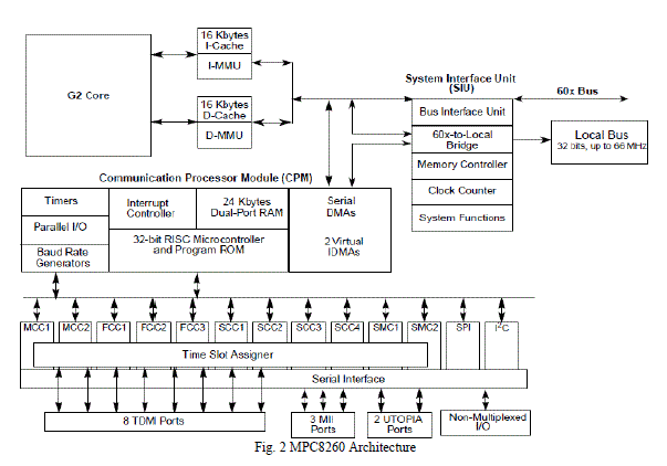
| JTAG controller IEEE 1149.1 test access support. The Communication Processor is an embedded 32 bit RISC controller residing on a separate bus. The Communication processor handles the lower layer tasks and DMA control activities, leaving the PowerPC core free to handle the higher layer activities. Figure 2 shows the block diagram of MPC8260 and its architecture [6] |
 |
III. CEREBRAL MODEL NEURAL NETWORK (CMNN)BASED CONTROLLER |
| Conventional feedback strategies can provide adequate performance only when the effects of non-linearityâÃâ¬ÃŸs are feeble. However most of the industrial process exhibit highly nonlinear behaviour. They may be operated over a wide range of conditioned due to disturbances and changes in set point. In such situations, conventional PID controllers must be tuned conservatively in order to provide stable behaviour over the entire range of operating conditions. This may result in serious degradation in performance. Recently, there has been a resurgence of interest in developing model based control system [2], [7]. In this method, the process model is explicitly used to predict future behaviour; it can be implicitly used (inverted) to evaluate the control action in such a way as to satisfy the controllers design specifications. The most expensive part of realization of model based schemes is the development of an appropriate mathematical model. In many cases it is even impossible to obtain a suitable physically founded processmodel due to complexity of the underlying process, or thelack of knowledge of critical parameters. |
| An effective alternative to overcome these problems is to use neural networks. Neural network models are derived from measured input-output data of the plant. They can approximate quite adequately the relationship between systems inputs and outputs, by learning without recourse to any prior mathematical formulation. |
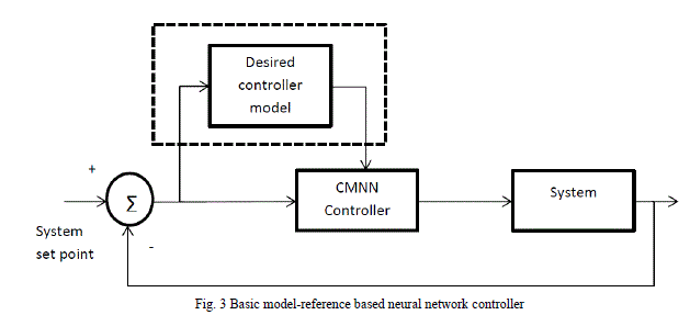 |
| A simple model-reference based neural network controller is implemented as shown in Fig. 3. In the proposed control system model, instead of having controllers loaded with specific algorithm , a general neural network based controller is assigned and trained to do the action of any type of controller [8], [9]. During the training period, if the controller is required to do the action of a PID controller, then during the training period, the error signal produced by the difference of setpoint and process output is given as input to both the CMNN based controller and the PID controller. The output of the actual controller is also an input to the CMNN controller during the training period. Instead of giving actual controller as the model to learn we can also train the neural network system based on any look up table which may not ideally represent a single control algorithm but a combination of different control strategies. Once the training period is over, the CMNN based controller will show better response when compared to any lookup table based controllers. Also there is an added advantage that the controller will interpolate the discrete values of the look-up table and provides a continues control function [10]. |
IV. COMMUNICATION WITH SENSORS AND ACTUATORS |
| Communication with the external device is achieved using RS-232 interface(serial port). RS-232 is a serial communication standard which uses a pair of cables to transfer data between two devices. Details such as character format and transmission bitrate are controlled by a special integrated circuit called UART which is present in both sending as well as receiving equipment. Details such as voltage level and slew rate are controlled by a device called line driver. Line driver converts between the logic levels of a UART and RS-232 compatible level. Even though the standard does not define transmission bitrate, it limits the maximum bitrate to 20000 bits per second. |
| VxWorks maintains a data structure called driver table. Each entry in the driver table is called a device descriptor, which corresponds to a particular hardware device. We can access serial port from the VxWorks application by using the device descriptor corresponding to serial port. Information in a device descriptor contains a device name string. Generally for serial port it will be like “/tyCo/1”. Where „tyCoâÃâ¬ÃŸ indicate the device type as serial port and „1âÃâ¬ÃŸ is used indicate a particular serial port if more than one serial port is present. This string can be used to gain access to the device by using open( ) system call. Open system call is a unix style general purpose system call used in most operating system. This can be used for opening a file or device. General format of this system call is as follows. |
| int open |
| ( |
| const char * name, |
| Int flags, |
| Int mode |
| ) |
| The first parameter is a character string. Which can be path to a file if the object need to be opened is a file, or a device string if it is a device. The second parameter is an integer for specifying the flags used for specifying the mode for opening the file, like read only, write only etc. Various flags are R RDONLY, O WRONLY, O RDWR, O CREAT. Third parameter is also an integer specifying the mode of file( in unixchmod style). If successful the function returns a file descriptor, which can be used in system call for further handling of file or device. if any error occurs during the execution of the function it returns ERROR. |
| The actual implementation of the open() systen call in this code is as follows, |
| f = open("/tyCo/1", O_RDWR, 0) |
| Here serial port is opened in read-write mode with unix style file mode as 0. File descriptor corresponding to serial port is stored in variable f. After opening the serial port successfully, the next task is to set the device parameters such as baud rate, parity etc. For this a system call called ioctl( ) is used here. The general format of an ioctl( ) function is described below. |
| intioctl |
| ( |
| intfd, |
| nt function |
| intarg |
| ) |
| Here the first parameter is the file descriptor return on successfulexecution of open() system call. And second parameteralso is an integer, specifying the function to be performed onthe I/O device. Third parameter is an arbitrary argument, whichchanges with the function to be performed. On successfulexecution it returns an integer value, indicating the status ofthe device. In the case of error an ERROR constant is returned. |
| The actual implementation used in this source code is as shown below, |
| status = ioctl(f, FIOBAUDRATE, 2400) |
| where f is the file descriptor corresponding to the openedserial port. FIOBAUDRATE is the function code specifyingthe function to be performed. In this case, it is to set the baudrate of the serial port to a particular value Third parameter isthe arbitrary argument and which in this case is the value ofthe baud rate. |
| After setting the baud rate of the serial port. Receiving the data through it is the next task. The read( ) system call provided by the VxWorks can be used for it. The general format of read( ) system call is explained below. |
| int read |
| ( |
| ntfd, |
| char * buffer |
| size_tmaxbytes |
| ) |
| Where fd is the file descriptor of the serial port, and bufferis a character pointer to buffer where the received data is tobe stored, and the last parameter is an integer indicating themaximum number of bytes to be read in to the buffer. Onsuccess, the function will return the number of bytes read into the buffer, otherwise ERROR. |
| After analyzing the data received from serial port control commands need to be send through serial port. For that write( ) system call provided by VxWorks is used. General format of which is described below. |
| int write |
| ( |
| intfd |
| char * buffer, |
| size_tnbytes |
| ) |
| As described above, fd is the file descriptor of the serial port,buffer is a character pointer pointing to the buffer containingthe data to be transmitted. the last parameter nbytes is thevariable indicating the number of bytes to be send to the serial port. On success the function returns the number of bytes written to the serial port. On error it returns ERROR constant. |
V. EXPERIMENTAL SETUP AND OBSERVED RESULTS |
| The proposed model was implemented using the experimental setup as shown in Fig. 4. |
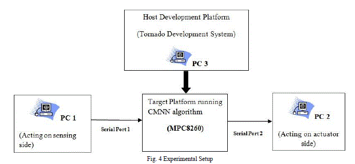 |
| Here, data coming from the sensor side is simulated by using a general purpose PC-1 running on Windows XP (SP- 1). PC-1 simulates sending data from two sensors S1 and S2. Data is sent using the hyper terminal application in Windows XP OS. This data is sent to the PowerPC through the UART module.PC-3 runs the Tornado development environment. Compiling and porting are done by using Tornado IDE 2.2.1 Suppliedalong with the embedded board. The board is connected tothe host machine running Tornado IDE, by using a LANcable and a serial cable. The serial cable is for controllingthe board through terminal, and LAN cable is for downloadingthe VxWorks image file, and application program. An FTP(filetransfer protocol) server program also is started in the hostmachine. Different IP addresses are assigned to both host andembedded board end of the LAN cable, and boot loader of theboard also is configured.For porting the CMNN applicationprogram, it should be compiled for the MPC8260 platform.The host based shell is started from the host machine, andCMNN application is started by typing the main function nameof the program in it. Once started, the program will functionas an CMNN based controller, which we can verify the results. |
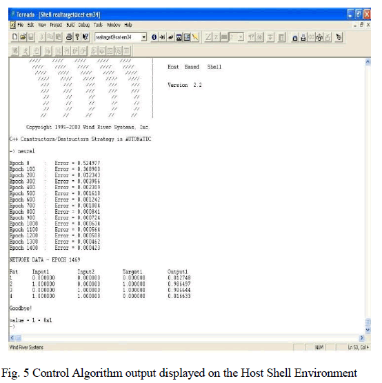
| CMNN controller is trained by giving a look-up table. To make the experiment setup simple a simple look-up which simulates an XOR gate is given as the the training set. Once training period is over, the MPC8260 will act as an XOR gate, which takes two information (Input1 and Input2) and provides an output 1 when only one of the input is high. It should be noted that such a simple algorithm was initially chosen just to demonstrate the flexibility of the proposed controller and to test the serial communication. A PID algorithm was also used to train the controller in the later stages, but results are presented only for the gate algorithm. |
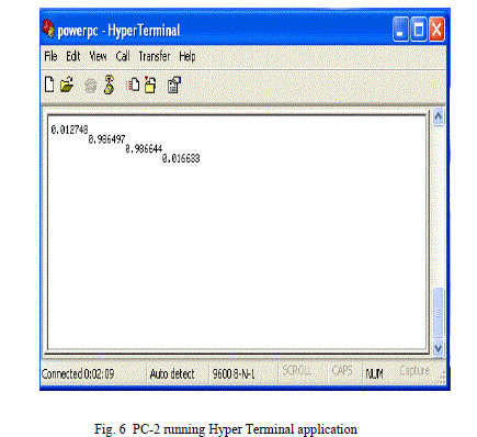
| Fig. 5 is the Host shell running on Tornado IDE in PC- 3. ItâÃâ¬ÃŸs clearly shows MPC8260 acting as an XOR gate taking inputs, Input1 and Input2. This control signal that the PowerPC generated is sent to the actuator, simulated by PC-2. PC-2 is running the hyper terminal application as shown in Fig. 6. It can be seen that the controller calculated value in the host shell and the value on hyper terminal on PC-2 are the same, confirming communication program. |
 |
 |
VI. CONCLUSION |
| A versatile CMNN based neural network controller was implemented and tested on a MPC8260 PowerPC ported with VxWorks RTOS. Sensors and actuators in the industry where simulated using two PCâÃâ¬ÃŸs and MPC8260 acted as a real world controller taking information from the process and providing the control function based on the process value. The calculated control action was given to the actuator which was simulated by PC-2. It was found that a CMNN based controller can be a general purpose alternative for single algorithm industrial controllers, as it can be trained to do any control algorithm. The performance of the proposed controller is at par with normal PID controller after training period. |
ACKNOWLEDGMENT |
| The authors would like to thank Dept. of Electronics and Communication, College of Engineering, Trivandrum for its facilities and whole hearted support. |
References |
|