ISSN ONLINE(2278-8875) PRINT (2320-3765)
ISSN ONLINE(2278-8875) PRINT (2320-3765)
A.Nithyanand1, D.Anitha1, S.Arul Prakash1, C.Naveen Kumar1
|
| Related article at Pubmed, Scholar Google |
Visit for more related articles at International Journal of Advanced Research in Electrical, Electronics and Instrumentation Engineering
This paper deals with the design of constant current controller for Photovoltaic (PV) power generator integrated with the grid. As the PV system uses the solar energy as one of the renewable energies for the electrical energy production as an enormous potential. The DC voltage generated by the PV system is boosted by DC-DC Boost converter. Maximum Power Point Tracking (MPPT) is used to track the maximum power for PV system. The utility grid is interconnected with the PV solar generator through the three phase PWM DC-AC inverter, whose control is provided by a constant current controller. This controller uses a three phase-Phase Locked Loop (PLL) to lock the grid frequency and phase. The low pass filter used to remove the high frequency ripple from the output; it seems to be efficient in supplying to load the constant voltage without phase jump. The complete mathematical model for the grid connected PV system is developed and simulated using MATLAB. The results verify that the proposed system is proficient to supply the local loads
Keywords |
| PV Solar Power Generator, DC-DC Boost Converter, PWM inverter, Phase Locked loop (PLL), Constant Current Controller (CCC). |
I. INTRODUCTION |
| The continuous increase in the electrical energy with the clean environment needs the decentralized renewable energy production. The increasing energy consumption may overload the distribution grid as well as power station and may cause the negative impact on power availability, security and quality. The only solution to overcome this problem is integrating the utility grid with the renewable energy systems like solar, wind or hydro. The grid1 can be connected to the renewable energy system as per the availability of renewable energy sources. Recently the solar power generation systems are getting more attention because solar energy is abundantly available, more efficient and more environment friendly as compared to the conventional power generation systems such as fossil fuel, coal or nuclear. The PV systems are still very expensive because of higher manufacturing cost of the PV panels, but the energy that drives them -the light from the sun is free, available almost everywhere and will still be present for millions of years, even all non-renewable energy sources might be depleted. One of the major advantages of PV technology is that it has no moving parts. Therefore, the PV system is very robust, it has a long lifetime and low maintenance requirements. And, most importantly, it is one solution that offers environmentally friendly power generation. The disadvantage of the PV system is that it can supply the load only in sunny days. Therefore, for improving the performance and supplying the power in all day, it is necessary to hybrid the PV system into another power generation systems or to integrate with the utility grid. |
| The integration of the PV system with the utility grid requires the PWM voltage source converter for interfacing the utility grid and results some interface issues. A prototype current controlled power conditioning system has been developed and tested. This prototype sources 20 kW of power from a photovoltaic array with a maximum power point tracking control. The disadvantage of this system is the need of high bandwidth current measurement transducers (dc to several times the switching frequency), and the need for relatively high precision in the reference signal generation. Hence, this increases the cost of the system. The inverters suitable for the PV system are central inverters, string inverters, Module integrated or module oriented inverters, multi string PV inverter with new trends has been described in [1]. If these solar inverters are connected with the grid, the control of these inverters can be provided using the phase locked loop [2]. The need and benefits of the distribution technology has been presented [3]. Singlephase Grid connected PV inverters with the control has been described with its advantages and disadvantages. The three-phase Photovoltaic power conditioning system with line connection has been proposed with the disturbance of the line voltage which is detected using a fast sensing technique. The control of the system is provided through the microcontroller [4, 5]. Power electronic systems can also be used for controlling the solar inverter for interfacing the Solar Power Generation system with the grid [6]. The complete design and modeling of the grid connected PV system has been developed to supply the local loads [7]. |
| This paper proposes the modeling of the grid connected PV system with the constant current controller (CCC), which controls the solar inverter for interfacing the grid. The voltage level of DC voltage generated by the PV array is increased using the boost converter and then applied to the 3-phase, 2_level solar inverter. The control of the solar inverter is provided through the constant current controller. This controller uses the Phase Locked Loop (PLL) and PI controllers. The PLL is used for tracking the phase angle of the grid voltage. The PI controller gains are chosen such that the CCC generates the pulses for solar inverter according to the grid voltage. |
 |
II. SYSTEM DESCRIPTION |
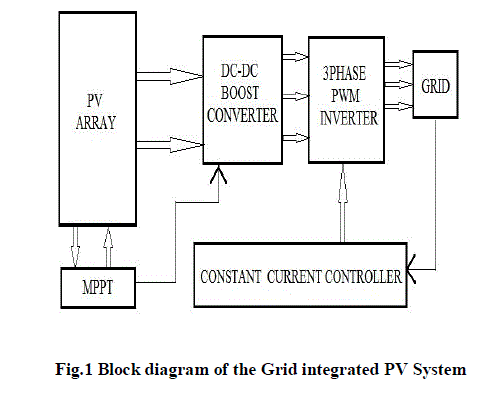
| Fig. 1 shows the configuration of the grid integrated PV system. The PV array is the combination of series and parallel connected PV module. Each PV module has series connected PV cell according to the voltage requirements. The MPPT technique is applied for operating the PV array at the maximum power point. The Vref generated by the MPPT is the desired DC voltage of the PV array and compared with the actual voltage of the PV array. The error signal is processed by the PI controller for minimizing the error. That control signal is compared with the triangular waveform for obtaining the switching pulses for the switch SW1. This arrangement controls the duty ratio for varying the load according to the MPPT.The boost converter stepping up the voltage level of the PV array. The 2-level inverter is inverting the DC voltage 600 V into the sinusoidal AC signal 415 V. A constant current controller is providing the switching pulses to the inverter. This controller senses the phase angle of the grid voltage and generates the switching pulses such that the inverter can output the voltage with the same frequency of the grid voltage. If there is phase distortion in the grid voltage, this controller is able to track the distorted phase and controls the inverter to give the same output. The harmonics generated by the inverter is reduced by the 3-phase LC filter. For integrating the PV system into the grid the voltage level should be same. Hence the 100kVA, 415/25 kV transformer is used. |
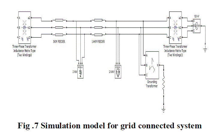
| The 120 kV, 2500 MVA utility grid is integrated with the solar system. The grid voltage level has been changed from 120 kV to the 25 kV using the step down transformer. The 30MW, 2-MVAr load is connected at the grid side. At the distance of 14 km resistive load of 2 MW is connected. At the distance of 5 km solar system has been connected. The grounding transformer is used for the protection against fault. The fault current is grounded by the grounding resistance RG. |
III. DESIGN DETAILS OF THE SYSTEM |
| A. MODELLING OF PV ARRAY |
| The Solar cells are the medium to convert solar energy into the electrical power. These cells are made up of semiconductor materials, when sun beam is absorbed with these material electrons emits and releases the current and thus electric power is produced. The equivalent circuit for obtaining the V-I and P-I characteristic of the PV cell is shown in the fig. 2. |
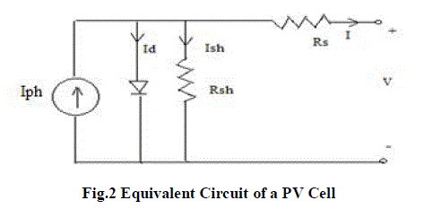 |
| From the PV equivalent circuit the current expression is obtained as |
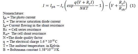 |
| The parameters (Iph, Rs, Rsh and N) vary with temperature and irradiance. Based on equation (1) PV cell model is simulated in SIMULINK There are two subsystems are present. One subsystem that calculates the PV cell photocurrent (Iph) depends on the irradiation and the temperature. Another subsystem that calculates reverse saturation diode current (Is) varies as a cubic function of temperature. Iph equation is expressed as |
 |
| Where Iscis cell short circuit current, Ki = 0.0017 A/âÃâæC is the temperature coefficient and β is the solar irradiation (W/m2).Based on equation (2). The diode reverse saturation current varies as a cubic function of the temperature and it can be expressed as |
 |
| where Isis the diode reverse saturation current, Tnom is the nominal temperature, Eg is the band gap energy of the semiconductor and Vt is the thermal voltage Based on equation (3) simulink model is developed. |
| The output obtained from the PV cell is very small. So, a number of cells are connected in series or parallel to form PV modules. The PV mathematical model used to simplify the PV module is represented by the equation |
 |
| Ns is total number of series cells and Np number of parallel connected cells. |
| B. BOOST CONVERTER MODEL |
| The output voltage of the PV cell is very limited, which is very low for the application. The series and parallel combination also does not provide the required output. Hence the boost converter is necessary to enable the low voltage PV array to be used. A capacitor is also connected for reducing the high frequency harmonics between the PV array and boost converter. Fig.3 shows the closed loop controller for boost converter. |
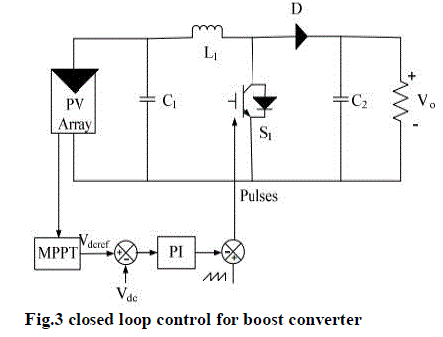 |
| When the switch S1 is in ON state, the inductor L1 is charged from the voltage (Vpv)generated by the PV array and the capacitor C1 discharges across the load. The duty cycle D is ((ton/t) and T); the boost converter operates in CCM (Continuous Conducting mode). The current supplied to the output RC circuit is discontinuous. Thus a large filter capacitor is used to limit the output voltage ripple. The filter capacitor must provide the output dc current to the load when the diode D is in OFF state. The control of the boost converter is provided through the PWM signal. The output of the filter which is the control signal is compared with the reference voltage. The PI controller attempt to minimize the error by adjusting the process control inputs. Then it is compared with the saw-tooth waveform to generate the PWM signal which is fed as gate signal to the IGBT switch. The control circuit regulating the reference voltage Vdcref , which is calculated by the MPPT techniques. Thus the PV array can be controlled by controlling the duty ratio for operating at the maximum power point. |
| C. PWM INVERTER |
 |
| A solar or PV inverter is interfacing the utility grid. It also converts the variable direct current output of a photovoltaic (PV) solar panel into a utility frequency alternating current that can be fed into a commercial electrical grid. It is a critical component in a photovoltaic system and its control should be such that its output can interface the voltage of the utility grid. |
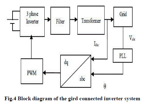
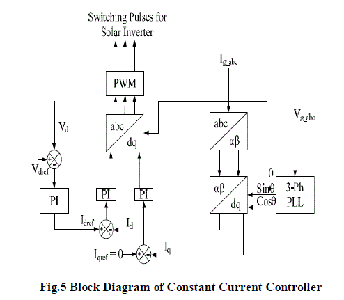
| There are two basic control modes for the grid connected inverters. One constant-current-control and the other is constant-power-control. In this proposed model, the control of the solar inverter is provided through the Constant Current Controller using the 3-phase(PLL). In constant current control, the inverter output currents are regulated to the reference grid current. Fig. 4 shows the switching model of the solar inverter. Fig.4 Switching Model of Solar Inverter Fig. 5 shows the detailed block diagram of the constant current controller for generating the controlled switching pulses for the solar inverter such that the output voltage should be able to interface the grid. The 3-phase_ Phase Locked Loop calculates the phase angle of the utility grid and also gives the information about the frequency variation. According to the phase angle of the utility grid voltage, the constant current controller is modeled such that the controller is able to generate the switching pulses for solar inverter for tracking the phase of the grid voltage. The 3-pahse grid current Ig_abc is converted into αβ variable using the Clarke transformation. The αβ variables are transformed into the dq variables. The current Id and Iq are compared with the Idref and Iqref for processing in the PI controller to minimize the errors. These signals are transformed into 3-_ signal using the inverse park’s transform and then compared with the triangular waveform for generating the PWM switching pulse for the solar inverter. The Vdc and Vdcref is the DC link voltage of the PV array and expected DC voltage of the PV array. |
| Fig. 5 shows the detailed block diagram of the constant current controller for generating the controlled switching pulses for the solar inverter such that the output voltage should be able to interface the grid. The 3-phase_ Phase Locked Loop calculates the phase angle of the utility grid and also gives the information about the frequency variation. According to the phase angle of the utility grid voltage, the constant current controller is modeled such that the controller is able to generate the switching pulses for solar inverter for tracking the phase of the grid voltage. The 3-phase grid current Ig_abc is converted into αβ variable using the Clarke transformation. The αβ variables are transformed into the dq variables. The current Id and Iq are compared with the Idref and Iqref for processing in the PI controller to minimize the errors. These signals are transformed into 3-pahse signal using the inverse park’s transform and then compared with the triangular waveform for generating the PWM switching pulse for the solar inverter. The Vdc and Vdcref is the DC link voltage of the PV array and expected DC voltage of the PV array. |
 |
| D. MPPT(PERTURBATION AND OBSERVATION) |
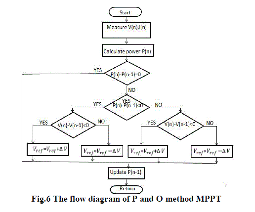
| P&O method is the most frequently used algorithm to track the maximum power due to its simple structure and fewer required parameters. This method finds the maximum power point of PV modules by means of iteratively perturbing, observing and comparing the power generated by the PV modules. It is widely applied to the maximum power point tracker of the photovoltaic system for its features of simplicity and convenience. According to the structure of MPPT system shown in Fig. 6, the required parameters of the power-feedback type MPPT algorithms are only the voltage and current of PV modules. Shown in Fig. 6 is the relationship between the terminal voltage and output power generated by a PV module. It can be observed that regardless of the magnitude of sun irradiance and terminal voltage of PV modules, the maximum power point is obtained while the condition dP/dV= 0 is accomplished. The slope (dP/dV) of the power can be calculated by the consecutive output voltages and output currents, and can be expressed as follows, |
 |
 |
| E. GRID INTERCONNECTED MODEL |
| A solar or PV inverter is interfacing the utility grid. It also converts the variable direct current output of a photovoltaic (PV) solar panel into a utility frequency alternating current that can be fed into a commercial electrical grid. It is a critical component in a photovoltaic system and its control should be such that its output can interface the voltage of the utility grid. Solar energy gathered by photovoltaic solar panels, intended for delivery to a power grid, must be conditioned, or processed for use, by a grid-connected inverter. This inverter sits between the solar array and the grid, draws energy from each, and may be a large stand-alone unit or may be a collection of small inverters, each physically attached to individual solar panels. The inverter must monitor grid voltage, waveform, and frequency. One reason for monitoring is if the grid is dead or strays too far out of its nominal specifications, the inverter must not pass along any solar energy. An inverter connected to a malfunctioning power line will automatically disconnect in accordance with safety rules. |
 |
IV. RESULTS AND DISCUSSION |
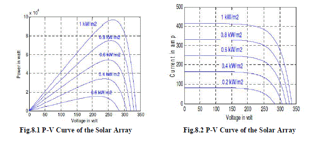
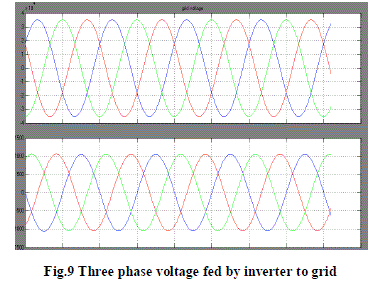
| In this paper, the simulation model proposes a 120 kV, 2500 MVA grid integrated solar system. Fig. 8.1 shows the PV array power generation at various solar irradiations. The PV array delivering a maximum of 100 kW at 1000 W/m2 sun irradiance. The PV array consists of 5 series connected modules per string and 66 parallel strings. There are 96 photovoltaic cells per module. Fig. 8.2 shows that the PV array generates voltage of about 321 V at 1000 W/m2. The 0pencircuit voltage (Voc) and short-circuit current (Isc) of one module is 64.2 V and 5.96 A respectively. The voltage and current at maximum power for one module is Vmp =54.7 V and Imp= 5.58 A respectively. The V-I and P-V curves are explaining the behavior of the PV array used in the proposed model. |
 |
 |
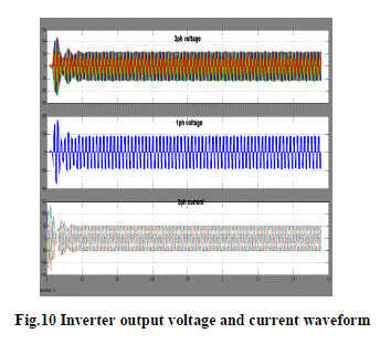
| The boost converter increasing voltage from PV natural voltage (300V DC at maximum power) to 600V DC voltage. Switching duty cycle is optimized by the closed loop controller that uses the PI controller according to load variation. The DC current and voltage delivered by the DC Boost converter is shown in the fig. 8.fig.9 Three phase voltage fed by inverter to grid. |
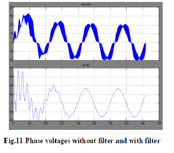
| For integrating the modeled solar generation system into the utility grid there is need of stepping up the voltage level from 415V to 25 kV. There is 2 MW load is connected using the 5km transmission line. Fig. 11 shows the load current for supplying the 2 MW load. |
  |
V.CONCLUSION |
| In this proposed method PV system is considered as a primary resource. This project, the detailed modeling of grid connected PV generation system is developed. The DC-DC boost converter is used to optimize the PV array output with the closed loop control for keeping the DC bus voltage to be constant. The 2 level 3-phase inverter is converting the DC into the sinusoidal AC voltage. The control of the solar inverter is provided through the constant current controller. This controller tracks phase and frequency of the utility grid voltage using the Phase Locked-Loop (PLL) system and generates the switching pulses for the solar inverter. Using this controller the output voltage of the solar inverter and the grid voltage are in phase. Thus the PV system can be integrated to the grid. After that the switching pulses will give to inverter and output will be achieved. And also analyse the controller will be suitable for all types of loads like linear and non-linear loads. |
References |
|