ISSN ONLINE(2278-8875) PRINT (2320-3765)
ISSN ONLINE(2278-8875) PRINT (2320-3765)
Shuchi Shah1
|
| Related article at Pubmed, Scholar Google |
Visit for more related articles at International Journal of Advanced Research in Electrical, Electronics and Instrumentation Engineering
Many existing and developing electrical and electronic technologies require voltages of different levels supplied from a singular available source voltage such as a battery. DC converters are devices designed specially for the purpose of changing DC voltage levels efficiently. The converters are electronic devices, it has an output voltage magnitude that is either greater than or less than the input voltage magnitude. Rising energy intensity leads to a higher cost of delivering power and low power density. Meanwhile, the demand for compact power supplies grows significantly. It requires power supplies with high efficiency, low cost and smaller size. In order to control the output voltage of the converter, the controller is designed to change the duty cycle of the converter. In this converter IGBT switch is digitally controlled by PIC microcontroller. In this work simulation and then hardware implementation is done with results. The converter is mainly used, where load is very sensitive (battery - powered products), it provides variation of _1% only.
Keywords |
| DC-DC converter, IGBT, PIC microcontroller, Boost level voltage, Buck level voltage. |
I.INTRODUCTION |
| DC - DC converters are electronic devices which used whenever we want to change DC electrical power efficiently from one voltage level to another. In High frequency switching converters, semiconductor devices switch at a rate that is fast compared to the variation of the input and output waveforms. High frequency switching converters are used most often as interfaces between DC systems of different voltage levels. These converters are known as high-frequency DC - DC converters. They are used in the power supplies and other electronic equipment. High frequency switching converters can also be used as an interface between DC and AC systems. In the fields of electrical engineering and applied physics, high voltage DC is required for several applications. |
| Such as electron microscopes, X-ray units require high DC voltages of the order of 100 kV or more, electrostatic precipitator, particle accelerators in nuclear physics and plasma research, railway coaches, drives, UPS system applications. |
| The converter is able to deliver output voltages both higher as well as lower than (or even equal to) the input voltage, this is why it is referred to as a buck-boost power converter. In many applications the input voltage can vary widely, starting at full charge and gradually decreasing as the battery charge is used up. At full charge, where the battery voltage may be higher than actually needed by the circuit being powered, a buck mode would be ideal to keep the supply voltage steady. However as the charge diminishes the input voltage falls below the level required by the circuit, and either the battery must be discarded or recharged at this point the ideal alternative would be the boost mode. |
| In this topology basically converter, flyback switched mode power supply is used with multiple secondary for supply of microcontroller and driver card operated at 25 kHz. IGBT is used as switch, operating at 6.4 kHz switching frequency. The input range of this DC to DC converter is 90 V-132 V & output range is 110 V, 50 A. IGBT switch is used in converter which is digitally controlled by PIC microcontroller. This controller adjust duty ratio and provides proper output. It is a RISC (Reduced Instruction Set Computer) design. |
II.SYSTEM MODEL AND ASSUMPTIONS |
| If we consider the system as 5.5 kW converter, flyback switched mode power supply is used with multiple secondary for supply of microcontroller and driver card operated at 25 kHz. IGBT is used as switch, operating at 6.4 kHz switching frequency. |
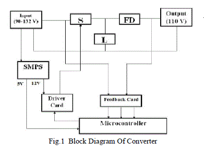 |
| IGBT switch is used in converter which is digitally controlled by PIC microcontroller. This controller adjust duty ratio and provides proper output. It is a RISC (Reduced Instruction Set Computer) design, only thirty seven instructions to remember. Its code is extremely efficient, allowing the PIC to run with typically less program memory than its larger competitors with low cost, high clock speed. |
III. DC-DC CONVERTER SYSTEM |
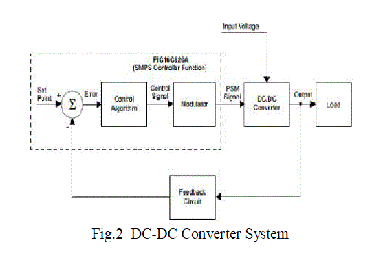
| Basically, two inductors are used for feeding the load by two independent switches. One inductor charges up by load voltages and another inductor discharges its energy into load during this time. The output power is almost doubled where the ripple voltage is reduced by factor of two when compared to the conventional DC to DC converter. If the supply side matter is concern then it includes Switched mode power supply and flyback converter with KA3524 SMPS controller. And according to the design parameters and results, simulation is done for getting reference values for the hardware implement with PIC Controller. |
 |
IV. SIMULATION RESULTS |
| Simulation results are carried out considering parameters like switch voltage, primary voltage, output current, output voltage and secondary voltage of Buck Boost Converter. Here in Figures, Simulation results are shown and according to this simulation result, reference values are being obtained and according to this values hardware results can be obtained. |
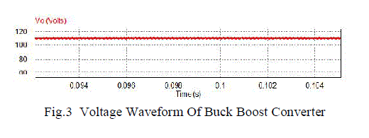 |
| Here in fig. 3, Voltage waveform of Buck Boost Converter is there which is obtained according to the input parameters variation occurs. If any change in input is there then the output voltage of Buck Boost Converter changes. |
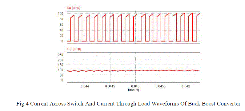 |
| Here in Fig. 4, Parameters changes in load tends to change the waveform of voltage and current across the switch of Buck-Boost converter. |
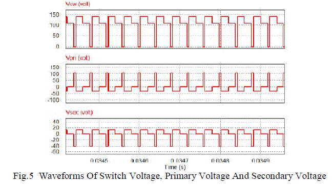 |
| Here in Fig. 5, It is shown that the the variation of the switches of the converter results should be observed at any instant so as variation occurs then voltage across switches, primary voltage, secondary voltage also changes and the final result is shown. |
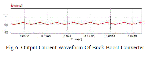 |
| Here in Fig. 6, Output voltage waveform of Buck Boost converter is there which is the final output result shown according to the particular requirement and application. |
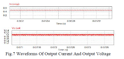 |
| Here in Fig.7, As any change in load, mains, parameters and switching instant occurs then obliviously change in output result is also occurs so the final waveform of output voltage and current is shown in the figure and the current value is around 0.5A and in voltage value is around 12V variation is there which is observed in the results. |
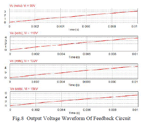
| Here in Figure 8, Output voltage waveform of feedback card is shown and according to this feedback circuit results, programming in PIC Controller is developed to obtained hardware results. |
 |
| Basically in DC to DC Buck Boost Converter system, Fly back SMPS is used to for power supply at certain frequency to supply voltage to control circuitry and driver circuitry respectively. In control circuit PIC 16F877A Controller is used and programming of this controller is done. Input voltage range can be varied between 90V-132V, with switching frequency around 6.4khz. |
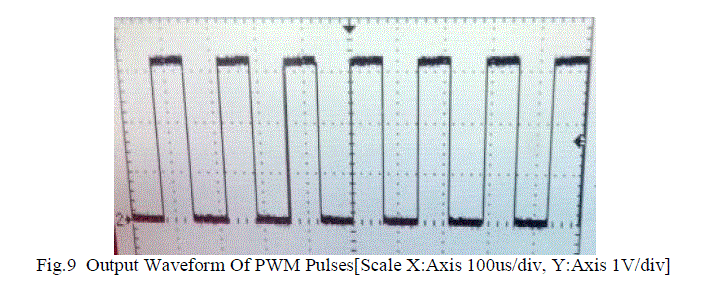 |
| Here in Figure 9, Output voltage waveform of PWM pulses is shown which is being obtained by PIC Controller for the analysis of Buck Boost converter system basically. |
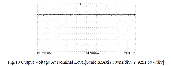 |
| Here in Fig. 10, nominal level output voltage is shown and according to the reference of the nominal level Buck and Boost voltage results are being obtained. |
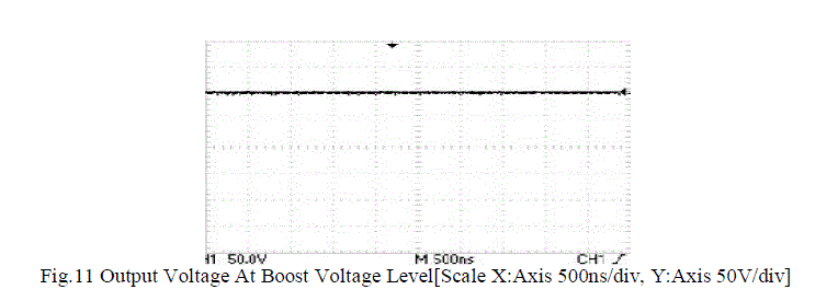 |
| Here in Fig.11, the output voltage at the Boost level is shown as per the reference of the nominal level. |
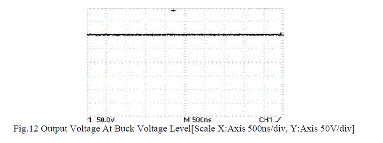 |
| Here in Fig.12, output voltage at Buck voltage level is shown according to the reference of the nominal voltage level as the final results. |
V.CONCLUSION |
| Rising energy density leads to higher cost of delivering power and low power density. This Buck Boost Converter system is being controlled by PIC Micro controller. High efficiency and low noise across 110V load was obtained. Simulation and hardware implementation can be easily done by interfacing with the PIC Micro controller with ADC and PWM analysis. The high power quality Buck Boost Converter is better solution for battery powered products. |
VI.ACKNOWLEDGMENT |
| The authors gratefully acknowledge the support of the Hitachi Hi-rel Power Electronics Pvt. Ltd., Gandhinagar in the development of the system and also the support of the Nirma University, Ahmedabad for platform. |
References |
|