ISSN ONLINE(2278-8875) PRINT (2320-3765)
ISSN ONLINE(2278-8875) PRINT (2320-3765)
S Kavin Joseph1, P.Rajakumar2
|
| Related article at Pubmed, Scholar Google |
Visit for more related articles at International Journal of Advanced Research in Electrical, Electronics and Instrumentation Engineering
This project presents a transformer less Distribution static synchronous compensator (DSTATCOM) system based on hybrid multilevel Hbridge converter with delta configuration. This hybrid multilevel DSTATCOM is characterized by per-phase series connection of a high-voltage H-bridge converter operating at fundamental frequency and a low-voltage H-bridge converter operating at 5 kHz without any other circuit for dc voltage control. A new control strategy is proposed in this project with focus on dc voltage regulation. Clustered balancing control is realized by injecting a zero-sequence current to the delta-loop, while individual voltage control is achieved by adjusting the fundamental content of ac quasisquare- waveform voltage of high-voltage converter. Index Terms—Multilevel inverter, Carrier Based PWM.
Index Terms |
| Multilevel inverter, Carrier Based PWM. |
I. INTRODUCTION |
| A cascaded H-bridge converter with equal dc voltage has been widely used for static synchronous compensator (STATCOM) application because of natural modular and high-quality output spectrum. Compared with diode-clamped converter and flying capacitor converter, the cascaded single-phase H-bridge converter saves a large amount of clamped diodes and flying capacitors. However, further improvement of power efficiency and waveform quality is expected of cascade H-bridge topology in highpower application. Traditionally, low-distorted ac voltage waveform is achieved by either increasing switching frequency or increasing the cascaded number of modules, which bring high power loss or high cost to the STATCOM system. Fortunately, hybrid multilevel technology provides a good tradeoff between waveform quality and switching loss. The important advantages of hybrid multilevel converters are as follows: increasing voltage levels of output waveform, improving ac current quality, reducing switching frequency resulting in low switching loss, as well as enhancing converter efficiency. |
| In this project, the authors focused on the STATCOM application using hybrid multilevel converters. The deltatype cascaded hybrid single-phase H-bridge topology is preferred because of modularity and simplicity. |
| This project proposed a new dc voltage control strategy for those hybrid multilevel converters. Clustered balancing control is achieved by injecting zero-sequence current to the delta-loop, and the individual voltage control is realized by trimming the fundamental content of quasisquare- wave voltage of high-voltage converters. Compared with other hybrid multilevel approaches, this control strategy along with the STATCOM system has the advantages of fast-speed response to load change, accurate unbalanced load compensation, no auxiliary circuit for dc links, less on-line calculation, specific unequal dc voltage regulation, as well as certain but unequal switching frequencies. |
II. NEED FOR MULTILEVEL VOLTAGE SOURCE INVERTER USING CASCADED-INVERTERS WITH SEPARATED DC SOURCES |
| The smallest number of voltage levels for a multilevel inverter using cascaded inverter with SDCSs is three. To achieve a three-level waveform, a single full-bridge inverter is employed. Basically, a full-bridge inverter is known as an H-bridge cell, which is illustrated in Fig. 3.1. The inverter circuit consists of four main switches and four freewheeling diodes. |
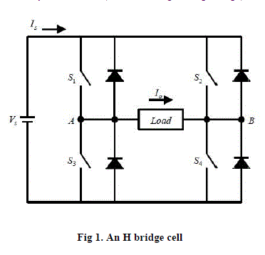 |
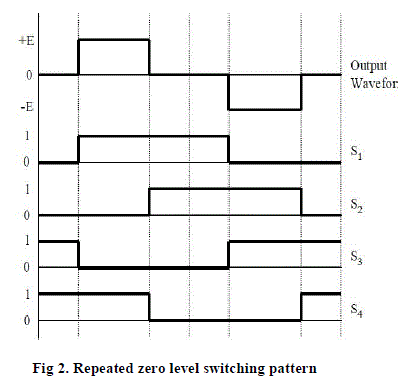
| According to four-switch combination, three output voltage levels, +V, -V, and 0, can be synthesized for the voltage across A and B. During inverter operation switch of S1 and S4 are closed at the same time to provide VAB a positive value and a current path for Io. Switch S2 and S4 are turned on to provide VAB a negative value with a path for Io. Depending on the load current angle, the current may flow through the main switch or the freewheeling diodes. When all switches are turned off, the current will flow through the freewheeling diodes. In case of zero level, there are two possible switching patterns to synthesize zero level, for example, 1) S1 and S2 on, S3 and S4 off, and 2) S1 and S2 off and S3 and S4 on. A simple gate signal, repeated zerolevel patterns. All zero levels are generated by turning on S1 and S2. Note that level 1 represents the state when the gate is turned on, and level 0 represents the state when the gate is turned off. In Fig. 2.1, S1 and S2 are turned on longer than S3 and S4 do in each cycle because the same zero level switching pattern is used. As a result, S1 and S2 are consuming more power and getting higher temperature than the other two switches. To avoid such a problem, a different switching pattern for zero level is applied. In the first zero stage, S1 and S2 are turned on; then, in the second zero stage, S3 and S4 are turned on in stead of S1 and S2. By applying this method, turn-on time for each switch turns out to be equal. This switching pattern will be used for experimental verification in this thesis. |
 |
III. PROPOSED BLOCK DIAGRAM |
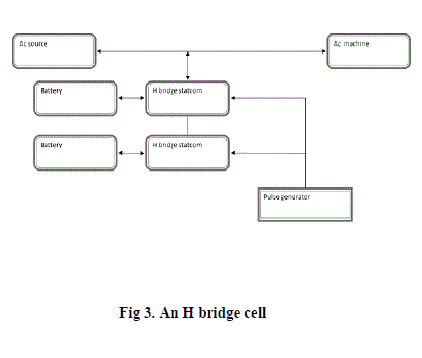
| The block diagram of proposed system consists of H-bridge converter STATCOM, AC input, pulse generator motor load and non linear load. Here, the function of STATCOM is control the transmission line power losses. |
 |
IV. STATCOM |
| It is a device connected in derivation, basically composed of a coupling transformer, that serves of link between the electrical power system (EPS) and the voltage synchronous controller (VSC), that generates the voltage wave comparing it to the one of the electric system to realize the exchange of reactive power. The control system of the STATCOM adjusts at each moment the inverse voltage so that the current injected In the network is in cuadrature to the network voltage,in these conditions P=0 and Q=0. This helps with compensation of negative phase current and with the reduction of voltage flicker. Active power control is possible with a STATCOM (with optional energy storage on dc circuit). This could further help with system stability control. |
V. RESULTS AND SIMULATION |
 |
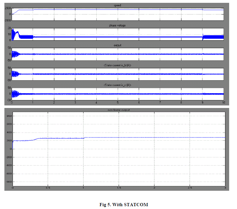
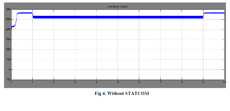 |
 |
 |
VI. CONCLUSION |
| This project has analyzed the fundamentals of dc voltage control based on cascaded hybrid multilevel H-bridge converters. And then, a hybrid modulation for hybrid multilevel converter has been proposed. The control scheme proposed in this project is characterized by the capability of maintaining the unequal dc voltage at the given value without any additional circuit, as well as by the ability of compensating serious unbalanced load. This control strategy has taken full advantages of the available switching devices by operating the highvoltage device at low switching frequency and lowvoltage device at high frequency. This control method along with the STATCOM system has the merits of producing high-quality output waveforms, reducing switching loss, and improving whole system’s efficiency. |