International Journal of Advanced Research in Electrical, Electronics and Instrumentation Engineering
ISSN ONLINE(2278-8875) PRINT (2320-3765)
ISSN ONLINE(2278-8875) PRINT (2320-3765)
Suneetha.Suddapalli, A.Raghuram
|
| Related article at Pubmed, Scholar Google |
Visit for more related articles at International Journal of Advanced Research in Electrical, Electronics and Instrumentation Engineering
In modern industrial and agricultural production, the sensor values change reflects the operating status of equipments and change of many physical characteristics, so the analog parameters like temperature is an important parameter, which needs to be monitored, especially in the severe environment. So it is the most effective and most economical means of equipment safety monitoring. A sensor values remote monitoring embedded system platform is designed in this project.LPC2148 micro controller is used as CPU of the system. The system realizes real-time remote data collection monitoring and storage through protocol data conversion of the CAN bus and USB bus of the distributed data acquisition node. The main aim of this project is to provide more safety to industry machines by avoiding operating from abnormal conditions of appliances like temperature, humidity, LDR. The controller Area Network (CAN) is a serial, asynchronous, Multi-master communication protocol for connecting electronic modules in Automotive and industrial applications.CAN protocol has many features like low cost, easy to implement, peer to peer network with powerful error checking and higher transmission rates 1Mbits.The CAN Network is a Peer to Peer Network consisting of different nodes. Different parameters can be monitored by these Nodes and can be updated to the Central Control Unit. Mostly used in Industry and Auto Mobiles in a Hazardous Environment and is reliable. Using CAN protocol we can send data from one node to other node. Here we are having two nodes, each node contains ARM7 based LPC2148 micro controller, MCP2515 (CAN CONTROLLER), MCP2551 (CAN TRANSRECEVER). In first node we are interfacing sensors, in second node contains PC. Node 1 will measure the sensor values and send these values to node 2 through CAN bus. This node 2 will display according to the data it received. The Can protocol is implemented using SPI lines of ARM7.
Keywords |
| CAN bus, ARM7 based LPC2148 micro controller |
I.INTRODUCTION |
| The Controller Area Network (CAN) bus has two communication formats: one is the 2.0A (standard-format), and the other is the 2.0B (extended-format). The CAN 2.0A format has an 11-bit identifier and the CAN 2.0B format has a 29- bit identifier. They can both be active in the same network to provide better flexibility in the integrated system. The main interface of CAN bus is for ISA or PCI, which is not widely applicable. The aim of this study was to design a convenient low-cost CAN-USB converter to control CAN devices using the USB port of a notebook or desktop computer. |
| Automotive industry uses Controller Area Network (CAN) as the in-vehicle network for the Engine Management, the body electronics like door and roof control, air conditioning and lighting as well as for the entertainment control. Nowadays all most all car manufacturers have also started implementing CAN based vehicle automation. CAN networks used in engine management to connect several ECUs. |
| In the proposed system, we are using temperature, amount of water vapour and lighting of the vehicle all are connected together using CAN controller and those data will be displayed on LCD as well as PC using HID terminal. |
II PROBLEM OUTLINE |
| Now a day we are using RS232 line to implement this project. RS232 is an old low speed serial bus communication protocol. The large voltage swings and requirement for positive and negative supplies increases power consumption of the interface and complicates power supply design. The voltage swing requirement also limits the upper speed of a compatible interface. In modern industrial and agricultural production, the sensor values change reflects the operating status of equipments and change of many physical characteristics, so the analog parameters like temperature is an important parameter, which needs to be monitored, especially in the severe environment. So it is the most effective and most economical means of equipment safety monitoring. |
III. OBJECTIVE OF THE PROJECT |
| The objective of this project is to design and develop the data receiving system using CAN-USB Converter Based on ARM7. |
| The objectives of this project are: |
| I. To study the basic operation of CAN controller. |
| II. To design and develop the CAN to USB data conversion |
| III. To design alert system using GSM system by sending vehicle whole information up to date. |
1V. SCOPE OF STUDY |
| The scope of study which is needed for the completion of this project involves the following criteria |
| 1. Architecture of LPC2148 knowledge |
| 2. ARM7 programming in C language. |
| 3. The study of modem functions which involves AT commands. |
| 4. The circuitry and devices that is needed to construct the devices and establish the necessary communication between the devices. |
| 5. The communication between CAN protocol and USB will be taken by the serial communication |
V. COMMUNICATION INTERFACES: USB AND WIRELESS PROTOCOLS |
| The key function of a controller for teleoperated robotic applications is to manage communications between the human operator and the robot. Doing so wirelessly gives the robot far more freedom. Communication interfaces (both wired and wireless) have progressed greatly and modern USB and wireless protocols offer many advantages for control systems. |
| Data transmission in most modern control systems is serial. Data is sent digitally and sequentially as a stream of bits on a minimum number of transmission lines (or wireless channels). Most microcontrollers are capable of automatically decoding serial transmissions either synchronously (with a clock signal) or asynchronously (with internal timing). Cabling and transmission between devices can be done with many protocols. In the past, RS-232 was the standard serial protocol, used by computers with 9-pin serial I/O ports. Universal Serial Bus (USB) offers a much faster, more reliable protocol and has replaced RS-232 as the standard interface. However, developing USB hardware and software is somewhat more difficult. |
VI.GSM MODULE |
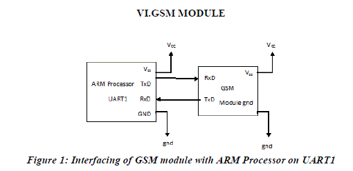 |
VII. CAN CONTROLLER |
| Microchip Technology’s MCP2515 is a stand-alone Controller Area Network (CAN) controller that implements the CAN specification, version 2.0B. It is capable of transmitting and receiving both standard and extended data and remote frames. The MCP2515 has two acceptance masks and six acceptance filters that are used to filter out unwanted messages, thereby reducing the host MCUs overhead. The MCP2515 interfaces with microcontrollers (MCUs) via an industry standard Serial Peripheral Interface (SPI). |
| The CAN module handles all functions for receiving and transmitting messages on the CAN bus. Messages are transmitted by first loading the appropriate message buffer and control registers. Transmission is initiated by using control register bits via the SPI interface or by using the transmit enable pins. Status and errors can be checked by reading the appropriate registers. Any message detected on the CAN bus is checked for errors and then matched against the user defined filters to see if it should be moved into one of the two receive buffers. |
VIII. REMOTE MONITORING USING WIRELESS SENSOR NETWORKS (WSN), BLUETOOTH, WIFI, ZIGBEE TECHNOLOGIES |
| systems using these technologies are popular due to flexibility, low operating charges, etc. Today Wireless Sensor Network are used into an increasing number of commercial.(Wijetunge et al., 2008) designed a general purpose controlling module designed with the capability of controlling and sensing up to five devices simultaneously. The communication between the controlling module and the remote server is done using Bluetooth technology. The server can communicate with many such modules simultaneously. The controller is based on ATMega64 microcontroller and Bluetooth communication TDK Blu2i (Class 1) module which provides a serial interface for data communication. The designed controller was deployed in a home automation application for a selected set of electrical appliances. |
| (Harms et al., 2010) describe the emerging wireless sensor networks (WSN) for autonomous Structural Health monitoring SHM systems for bridges. In SmartBrick Network, the base station and sensor nodes collect data from the onboard and external sensors. The sensor nodes communicate their data from quasi-static sensors, e.g., temperature sensors, strain gauges and seismic detectors to the base station over the ZigBee connection. The base station processes these data and communicates them, along with any alerts generated, to a number of destinations over the GSM/GPRS link provided by the cellular phone infrastructure. |
IX. APPLICATION AREAS |
| Nearly 99 per cent of the processors manufactured end up in embedded systems. The embedded system market is one of the highest growth areas as these systems are used in very market segment- consumer electronics, office automation, industrial automation, biomedical engineering, wireless communication, data communication, telecommunications, transportation, military and so on. |
| Consumer appliances: At home we use a number of embedded systems which include digital camera, digital diary, DVD player, electronic toys, microwave oven, remote controls for TV and air-conditioner, VCO player, video game consoles, video recorders etc. Today’s high-tech car has about 20 embedded systems for transmission control, engine spark control, air-conditioning, navigation etc. Even wristwatches are now becoming embedded systems. The palmtops are powerful embedded systems using which we can carry out many general-purpose tasks such as playing games and word processing. |
| Office automation: The office automation products using embedded systems are copying machine, fax machine, key telephone, modem, printer, scanner etc. |
| Insemination: Testing and measurement are the fundamental requirements in all scientific and engineering activities. The measuring equipment we use in laboratories to measure parameters such as weight, temperature, pressure, humidity, voltage, current etc. are all embedded systems. Test equipment such as oscilloscope, spectrum analyzer, logic analyzer, protocol analyzer, radio communication test set etc. are embedded systems built around powerful processors. Thank to miniaturization, the test and measuring equipment are now becoming portable facilitating easy testing and measurement in the field by field-personnel. |
| Security: Security of persons and information has always been a major issue. We need to protect our homes and offices; and also the information we transmit and store. Developing embedded systems for security applications is one of the most lucrative businesses nowadays. Security devices at homes, offices, airports etc. for authentication and verification are embedded systems. Encryption devices are nearly 99 per cent of the processors that are manufactured end up in~ embedded systems. Embedded systems find applications in . every industrial segment- consumer electronics, transportation, avionics, biomedical engineering, manufacturing, process control and industrial automation, data communication, telecommunication, defence, security etc. Used to encrypt the data/voice being transmitted on communication links such as telephone lines. Biometric systems using fingerprint and face recognition are now being extensively used for user authentication in banking applications as well as for access control in high security buildings. |
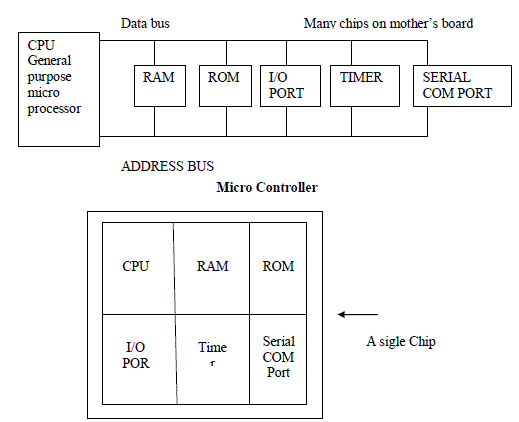
X. GENERAL MICRO PROCESSOR |
| 1. cpu for computers |
| 2. No RAM, ROM, I/O on CPU chip itself |
| 3. Example : Intel’s x86 |
 |
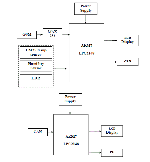
XI. Block Diagram of the Project and its Description |
| The block diagram of the design is as shown in Fig 4.1. It consists of power supply unit, microcontroller, CAN, GSM, Sensors (temperature, humidity, LDR), LCD. The brief description of each unit is explained as follows. |
| BLOCK DIAGRAM: |
 |
| 1. Implements CAN V2.0B at 1 Mb/s: |
| a. 0 – 8 byte length in the data field |
| b. Standard and extended data and remote frames |
| 2. Receive buffers, masks and filters: |
| a. Two receive buffers with prioritized message storage |
| b. Six 29-bit filters |
| c. Two 29-bit masks |
| 3. Data byte filtering on the first two data bytes (applies to standard data frames) |
| 4. Three transmit buffers with prioritizaton and abort features |
| 5. High-speed SPI Interface (10 MHz): |
| a. SPI modes 0,0 and 1,1 |
| 6. One-shot mode ensures message transmission is attempted only one time |
| 7. Clock out pin with programmable prescaler: |
| a. Can be used as a clock source for other device(s) |
| 8. Start-of-Frame (SOF) signal is available for monitoring the SOF signal: |
| a. Can be used for time-slot-based protocols and/or bus diagnostics to detect early bus degredation |
| 9. Interrupt output pin with selectable enables |
| 10. Buffer Full output pins configurable as: |
| a. Interrupt output for each receive buffer |
| b. General purpose output |
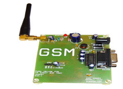
XII. GSM MODEM |
| This GSM Modem can accept any GSM network operator SIM card and act just like a mobile phone with its own unique phone number. Advantage of using this modem will be that you can use its RS232 port to communicate and develop embedded applications. Applications like SMS Control, data transfer, remote control and logging can be developed easily. The modem can either be connected to PC serial port directly or to any microcontroller. It can be used to send and receive SMS or make/receive voice calls. It can also be used in GPRS mode to connect to internet and do many applications for data logging and control. In GPRS mode you can alsoconnect to any remote FTP server and upload files for data logging. This GSM modem is a highly flexible plug and play quad band GSM modem for direct and easy integration to RS232 applications. Supports features like Voice, SMS, Data/Fax, GPRS and integrated TCP/IP stack. |
 |
XIII. LIQUID CRYSTAL DISPLAY |
| LCD stands for Liquid Crystal Display. LCD is finding wide spread use replacing LEDs (seven segment LEDs or other multi segment LEDs) because of the following reasons: |
| 1. The declining prices of LCDs. |
| 2. The ability to display numbers, characters and graphics. This is in contrast to LEDs, which are limited to numbers and a few characters. |
| 3. Incorporation of a refreshing controller into the LCD, thereby relieving the CPU of the task of refreshing the LCD. In contrast, the LED must be refreshed by the CPU to keep displaying the data. |
| 4. Ease of programming for characters and graphics. |
| These components are “specialized” for being used with the microcontrollers, which means that they cannot be activated by standard IC circuits. They are used for writing different messages on a miniature LCD. |
XIV. RESULTS AND DISCUSSIONS |
| A) Results |
| The implementation and realization of “DESIGN AND IMPLEMENTATION OF ENVIRONMENT MONITORING AND DEVICE CONTROL USING CAN-PROTOCOL” is done successfully. The communication is properly done without any interference between different modules in the design. Design is done to meet all the specifications and requirements. Software tools like keil uvision simulator, proload to dump the source code into the microcontroller, orcad lite for the schematic diagram have been used to develop the software code before realizing the hardware. Circuit is implemented in Orcad and implemented on the microcontroller board. The performance has been verified both in software simulator and hardware design. The total circuit is completely verified functionally and is following the application software. It can be concluded that the design implemented in the present work provide portability, flexibility and the data transmission is also done with low power consumption. |
B) CONCLUSION |
| An effective solution is provided to develop a low cost CAN-USB converter, which is capable of receiving CAN data and controlling CAN device via the USB port of a desktop or notebook computer. Here electrical parameters are controlled by using CAN controller in industries and vehicles with sensor system like temperature, light, humidity. |
References |
|