ISSN ONLINE(2278-8875) PRINT (2320-3765)
ISSN ONLINE(2278-8875) PRINT (2320-3765)
K. Delhi Prasad1, S.Senthil2
|
| Related article at Pubmed, Scholar Google |
Visit for more related articles at International Journal of Advanced Research in Electrical, Electronics and Instrumentation Engineering
This paper presents the virtual environment implementation for project simulation and conception of supervision and control systems for mobile robots, which are capable of operating and adapting in different environments and conditions. The purpose of this virtual system is to facilitate the development of embedded architecture systems, emphasizing the implementation of tools that allow the simulation of the kinematic conditions, dynamic and control, with real time monitoring of all important system points. To accomplish this, open control architecture is proposed, integrating the two main techniques of robotic control implementation in the hardware level: systems microprocessors and reconfigurable hardware devices. The utilization of a hierarchic and open architecture, distributing the diverse actions of control in increasing levels of complexity, the use of resources of reconfigurable computation are made in a virtual simulator for mobile robots.
Keywords |
| Hard Ware Level, Mobile Robot, Kinematic Conditions, Microprocessor |
I. INTRODUCTION |
| The main objective of this work is to present a proposal of a virtual environment implementation for rapid prototype project and simulation with conception of supervision and control systems for mobile robots. Those mobile robots platform are capable to operate and adapting at different environments and conditions. The purpose of this virtual system is to facilitate the development of embedded architecture systems, emphasizing the implementation of tools that allow the simulation of the kinematic conditions, dynamic and control, with real time monitoring of all important system points. In the way to accomplish these tasks, open control architecture |
| is proposal, integrating the two main techniques of robotic control implementation in the hardware level: microprocessors systems and reconfigurable hardware devices. The utilization of a hierarchic and opened architecture, distributing the diverse actions of control in increasing levels of complexity, the use of resources of reconfigurable computation and the validation of this environment are made in a virtual simulator for mobile robots. |
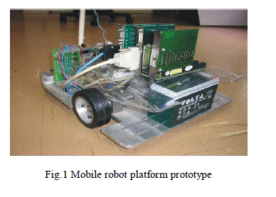
| Within the proposal of platform mobile robotics, the use of an embedded processor, with control software especially developed for the necessary applications is considered. The objective of this platform is to make use of the existing communication interfaces, as well as to provide an embedded user interface alternative in the mobile robot. Another aspect considered, is the flexibility of the hardware project, which allows the expansion of mobile robot facilities. This paper focuses on the study of the mobile robot platform, with differential driving wheels mounted on the same axis and a free castor front wheel, whose prototype used to validate the proposal system, is depicted in Fig. 1. Mobile robot platform illustrates the platform. |
 |
LITERATURE SURVEY |
| The Different Types of Embedded Car is reviewed from this reference paper, G. Pandian and S. Rama Reddy, “Embedded Controlled Z Source Inverter Fed Induction Motor Drive” IEEE transaction on industrial application, vol.32, no.2, May/June 2010. The Embedded programming structures is analyzed from this reference book, 8051 microcontroller and Embedded systems using assembly and C by Muhammad Ali mazidi, Janice Gillispie Mazidi and Rolin D.Mckinlay. |
| Designing of controllers is gathered from this reference paper, K.Niraimathy, S.Krithiga, “A New Adjustable-Speed Drives (ASD) System Based On High-Performance Z-Source Inverter”, 978-1-61284-379-7/11 2011 IEEE, 2011 1st International Conference on Electrical Energy Systems. Types of PWM Generation is designed by this reference paper, Omar Ellabban,Joeri Van Mierlo and Philippe Lataire, “Comparison between Different PWM Control Methods for Different Inverter Topologies” IEEE Transactions on industry application, May/June 2010 |
II. MOBILE ROBOT MODELING |
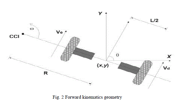
| Suppose that the robot is at some position (x; y) and “facing” along a line making an angle _ with x axis (Fig. 2). Through manipulation of the control parameters ve and vd, the robot can be made to take on different poses. Determining the pose that is reachable given the control parameters is known as the forward kinematics problem for the robot |
 |
| A. Inverse kinematics for differential drive robots |
| Equation 3 describes a constraint on the velocity of the velocity of the robot that cannot be integrated into a positional constraint. this is known as a non holonomic constraint and is very difficult to solve in general, although solutions are straightforward for limited classes of the control functions ve(t) and vd(t). For example, if it is assumed that, |
 |
| Where (x; y; _) t=0 = (0; 0; 0). Given a goal time t and goal position (x; y). Equation 4 solves for vd and ve but does not provide for independent control of. There are actually infinitely many solution for vd and ve from Equation 4, but all correspond to the robot moving about the same circle that passes through (0; 0) at t = 0 and (x; y) at t = t; however, the robot goes around the circle different numbers of times and in different directions. |
III. PROPOSED SYSTEM |
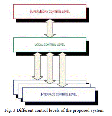
| The proposed system can be visualized at a logical level in the blocks diagram in Fig. 3. The system was divided into three control levels, organized in the form of different degrees of control strategies. The levels can be described as: |
| Supervisory control level: This represents a high level of control. In this level it was possible to carry out the supervision of one or more mobile robots, through the execution of global control strategies. |
| Local control level: In this level control was processed by the mobile robot embedded software implemented in a 8 bits microcontroller. The control strategies allowed decision making to be done at a local level, with occasional corrections from the supervisory control level. Without communication with the supervisory control level, the mobile robot just carried out actions based on obtained sensor data and on information previously stored in its memory. |
 |
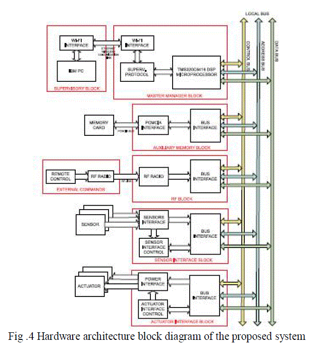 |
| Interface control level: This was restricted to strategies of control associated with the interfaces of the sensor and actuators. The strategies in this level were implemented in hardware, through PLD (Programmable Logic Devices). Architecture, from the point of view of the mobile robot, was organized into several independent blocks, connected through the local bus that is composed by data, address and control bus (Fig. 4). |
| A master block manager operates several slave blocks. Blocks associated with the interfaces of sensors and actuators, communication and auxiliary memories were subjected to direct control from the block manager. The advantage of using a common bus was the facility to expand the system. Inside the limitations of resources, it was possible to add new blocks, allowing an adapted configuration of the robot for each task. |
| A. Description of blocks |
| • Supervisory control block: Is the high level of control. In this block is managed the supervision of one or more mobile robots, through the execution of global control strategies. Is implemented in an IBM PC platform and is connected with the local control level, in the mobile robot, through Ethernet wireless WI-FI link. This protocol uses IEEE 802.11a standard for wireless TCP/IP LAN communication. It guarantees up to 11 Mbps in the 2.4 GHz band and requires fewer access points for coverage of large areas. Offers high-speed access to data at up to 100 meters from base station. 14 channels available in the 2.4 GHz band guarantee the expansibility of the system with the implementation of control strategies of multiple robots. |
| • Master Manager block: Responsible for the treatment of all the information received from other blocks, for the generation of the trajectory profile for the local control blocks and for the communication with the external world. In communication with the master manager block, through a serial interface, a commercial platform was used, which implemented external communication using an Ethernet WI-FI wireless protocol. The robot was seen as a TCP/IP LAN point in a communication net, allowing remote supervision through supervisory level. It’s implemented with Texas Instrument TMDSDSK6416 DSP board Kit that uses the TMS320C6416 DSP, a 1GHz device delivering up to 8000 million instructions per second (MIPs) with highest performing. The C6416 is based on the high performing |
| TMS320C6400 DSP platform designed to needs of high-performing memory intensive applications such as networking, video, imaging, embedded systems controllers and most multichannel Systems. |
| Sensor interface block: Is responsible for the sensor acquisition and for the treatment of this information in digital words, to be sent to the master manager block. The implementation of that interface through PLD allowed the integration of information from sensors (sensor fusion) locally, reducing manager block demand for processing. In same way, they allowed new programming of sensor hardware during robot operation, increasing sensor treatment flexibility. |
| Actuator interface block: This block carried out speed control or position control of the motors responsible for the traction of the mobile robot. The reference signals were supplied through bus communication in the form of digital words. Derived information from the sensor was also used in the controller implemented in PLD. Due to integration capacity of enormous hardware volume, PLD was appropriate to implement state machines, reducing the need for block manager processing. Besides the advantage of the integration of the hardware resources, PLD facilitated the implementation and debugging. The possibility of modifying PLD programming allowed, for example, changes in control strategies of the actuators, adapting them to the required tasks. |
| Auxiliary memory block: This stored the information of the sensor, and operated as a library for possible control strategies of sensors and actuators. Apart from this, it came with an option for operation registration, allowing a register of errors. The best option was an interface PCMCIA, because this interface is easily accessible on the market, and being a well adapted for applications in mobile robots, due to low consumption, little weight, small dimensions, high storage capacity and good immunity to mechanical vibrations. |
| RF communication Block: It allowed the establishment of a bi-directional radio link for data communication. It is used for the mobile robot to receive operation commands, allowing the learning of trajectories, for example. It operated in parallel with the commercial platform WIFI link. The objective of these communication links was to allow the use of remote control. All the commands executed from the remote control are analyzed from master block manager to guarantee the best trajectory strategy. The remote control has a high trajectory priority from other blocks, like supervisory control block, and can take the control of the mobile robot to execute, for example, emergency necessary movements or stop. To implement this block was used a low power UHF data transceiver module BiM-433-40. It is a miniature UHF radio module capable of half duplex data transmission at speeds up to 40 kbit/s over distances of 30 meters ”in-building” and 120 meters open ground. The module was chosen because it integrates a low power UHF FM transmitter and matching super- heterodyne receiver together with the data recovery and TX/RX change over circuits to provide a low cost solution to implementing a Bi-directional short-range radio data link. |
IV. MOBILE ROBOT SIMULATOR |
| The complete simulator system for the wheeled mobile robot, including motor drives, gears, kinematics and dynamics model, and controllers can be modeled in the same diagram using blocks from the Electric Drives library and SIMULINK libraries. The purpose of the following experiments is to implement a simulator robot position control, based in This architecture was sufficiently generic to be used with several models of mobile robots. As an initial validation, the use of a platform with a differential drive configuration was proposed. |
| A great number of sensors could equally been used, but two types were initially considered: |
| • Position sensor: Two encoders responsible for the odometry information. |
| • Range finder sensor: Responsible for the distance measured to obstacles in front and on the side of the Mobile robot |
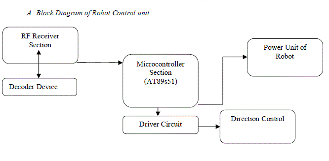
| A. Block Diagram of Robot Control unit: |
 |
| B. Platform Model Proposed: |
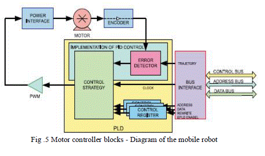
| At the platform model proposed (Fig. 4), the encoders were coupled directly to the axis of the motor, allowing for a larger resolution in odometry measurements. The range finder sensors were distributed to cover the probable areas of collision. An example of flexibility provided by FPGA was illustrated in the speed and position control of the traction axis of the mobile robot, the aim of which is a DC motor control powered by a PWM drive. This programmable controller worked directly with digital signals generated by the encoder coupled to the motor and generated by the local control level, representing a trajectory. Fig. 5 represents the proposed controller, with the various proposed control levels. PLD allowed this controller to be implemented in different ways, applying different control strategies. The controller can be, for example, a PID, an adaptive controller or a predictive controller. In this case, information coming from the encoder direction or from the range finder sensor can be used as additional signal to the controller. The implementation of digital controller (RST form) is realized using libraries built for algebraic manipulation in VHDL. |
 |
| D. Axis Control Architecture: |
| One advantage of the virtual environment is the possibility to implement and test advanced axis control strategies, in particular Generalized Predictive Control, well known structure providing improved tracking performances. This philosophy aiming at creating an anticipative effect is using the explicit knowledge of the trajectory in the future |
VI. DESIGN OF HARDWARE |
| The Robot Car used as experimental validation of the proposed system has been improving for quadriplegic user’s better navigation. It was implemented by the researching group in the way it can navigate in a semiautonomous mode, indoor and outdoor. With a set of ultrasonic sensors, laser beam sensor, solid state compass, accelerometer sensors, among others, the wheelchair is capable to provide an ideal platform to test and validate the secure navigation system, proposed in this work. The supervision and the chair movement coordination are made through a close loop architecture based in a satellite camera over the environment. The information supplied for a video camera is sent for one or two computers for processing. The data obtained from this process are used to generate a sequence of instructions that are sent for the wheelchair. The chair receives the instructions and carries through the actions obeying the predetermined tasks. The instructions are results of developed programmers’ strategies to execute the tasks and to realize the chair navigation into the environment. This trajectory allows getting parameters of comparison between the real system, represented by robot prototype, and the virtual system. |
| A) Directions of the Robot Car: |
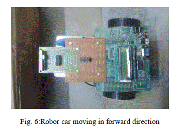 |
| When the Robot car making an angle =90 degrees the car moving in forward direction based up on the angle of the robot car the Car direction changes with the use of controller.The controller having transmitter and reciever, Transmitter which transmits the signals through the sensors and receiver receives the signalsand moving the Car in the required direction. |
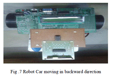 |
| When the Robot car making angle =-90 degrees the car moving in backward direction based up on the angle of the Car direction changes with the use of Controller .The Controller having the transmitter and receiver, transmitter which transmits the signals through the sensors and receives the signals and moving the car in required direction. |
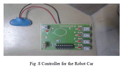 |
| Above fig represents the controller of the Robot Car which having four Control levels each button having a Specific operation , based on the Signals generating by the Controller the Robot Car moves Forward ,Backward ,Left and Right directions |
| B ) Applications |
| Military navigation |
| Global navigation |
| Local navigation |
| Person navigation |
VIII. CONCLUSION |
| The main objective of this work is to propose a virtual environment implementation for project simulation and conception of supervision and control systems for mobile robots, which are capable of operating and adapting in different environments and conditions. For this, a generic platform for a robotic mobile system and a wheelchair, seeking to obtain a support tool for under-graduation and graduation activities was used to validate the results. This came from encountering the growing need to propose to the research that integrates |
| Flexibility - there was a great variety of possible configurations in the implementation of solutions for Several problems associated with mobile robots. |
| Great capacity of memory storage allowing implementation of sailing strategies for maps. |
| Possibility of modification of control strategies during the operation of the mobile robot in special mechatronics applications. |
References |
|