ISSN ONLINE(2278-8875) PRINT (2320-3765)
ISSN ONLINE(2278-8875) PRINT (2320-3765)
G.Mohanambal1, R.Yamini2, S.Shanthi1, S.Janani1
|
| Related article at Pubmed, Scholar Google |
Visit for more related articles at International Journal of Advanced Research in Electrical, Electronics and Instrumentation Engineering
The HID lamps are extensively more efficient at producing evident light for a given amount of electrical power than fluorescent or incandescent bulbs. The HID lamps are used, when high levels of brightness and energy efficiency are required. Electronic ballast for driving high intensity discharge (HID) lamps consisting of fly back converter is used in this work. In fly back converters dc supply is switched at very high frequency and inductively transferred to dc load via a high frequency transformer and rectifier. This concept is utilized in this work to charge and discharge two capacitors alternatively using two power switches connected to primary and secondary of a high frequency transformer. In adding EMI filter (Electromagnetic Interference Filter) can be additional to prevent the intrusion of generated high frequency with 50Hz supply. Pf, Power and effectiveness calculations are also performed. Closed loop PID control is also provided to attain the preferred output voltage .A prototype consisting of a sensing circuit fully referenced to the switches general ground is explained in detail. Design conformity, experimental and simulation results from Matlab and CCS are presented, as well as deliberations about the converter possibility are done
Keywords |
| Feedback, Fly back, filter, rectifier, controller, HID lamp. |
I.INTRODUCTION |
| High-Intensity discharge (HID) lamps are recently used due to their known advantages over other lighting sources in several applications. Long lifetime and high luminous efficiency, achieving greater than 100 lm/W, are two important characteristics. It is well-known that lighting shows a major component of energy consumption. Around 19% of global power consumption and 3% of global oil demand is characteristics to lighting. Since then the electric bulb was invented by Thomas Edison, many important energy-saving lighting products have been invented. Nowadays there are nearly 6,000 various kinds of lamps being manufactured can be placed three categories: i.e.) incandescent lamp, Mercury lamp, and light-emitting diode (LED). |
| Incandescent lamps, gas discharge lamps and LEDs produce light through different physical process of electrical energy conversion. Incandescent lamps are based on the Joule-heating process .From these process electrically heating high-resistance tungsten filaments which generate intense brightness. The lamp current is dictated by the applied voltage and the resistance of the tungsten filament, which is closed to the v-i characteristic of a linear resistor. The total amount of energy radiated from incandescent lamps spectrum is continuous with color rendering However, incandescent lamps normally have low efficiency and only around 10% of the electrical energy flowing through incandescent lamps is converted to light. |
| The Gas-discharge lamp yield light by passing an electrical discharge through an ionized gas. I.e. plasma. Usually, such lamps are prepared with both gracious gases and metals, such as mercury, sodium, or metal halides. Then, the metal produces the light once they are heated to a specific point. During process the gas is ionized and free electrons, speeded up because of electrical field in the tube, where the gas and metal atoms crash with each other. Few electrons flowing around the gas and metal atoms are stimulated by these collisions; carry them to a higher energy state. While the electrons come back to the original state it emits a photon which produces an ultraviolet radiation or visible light. Ultraviolet radiation is converted to visible light by a fluorescent coating on the inside of the lamp's glass surface for some lamp types. An LED is a semiconductor diode that emit light when an electric current is apply in the forward path due to the result of electroluminescence the p-n junction emits incoherent and narrow-spectrum light. An LED is normally a small-area light source of less than 1 mm2, often with optics additional to the chip to shape its radiation model and support in reflection. The color of the emitted light depends on the semiconducting material when we used, and it can be infrared, visible, or ultraviolet. LEDs are normally used as indicator lights on electronic devices and increasingly in higher-power applications like flashlights and area lighting. Because single LEDs are low-voltage DC devices, operating from AC mains needs well-designed circuitry and a thermal case to dissipate the heat. |
| Common parameters used to calculate lamp quality include luminous efficiency, typical lamp life, and color rendering index. Luminous efficiency is the most significant property of light sources, which shows the fraction of electromagnetic power which is helpful for elucidation. It is the fraction of emitted luminous flux to radiant flux, and is calculated by lumens per watt (lm/W). Light with wavelengths outside the visible spectrum decreases luminous efficiency, because the light with not able to be seen wavelengths contribute to the radiant flux, while the luminous flux of this light is zero. Typical lamp life time is the number of hours it takes for roughly 50% of a large group of lamps of the similar type to fail. If the lamp not work properly there is no longer light the color rendering index (CRI) is a quantitative compute of the capability of a light source to replicate the colors of different substance faithfully in evaluation with an ultimate or natural light source. Incandescent lamp depends on the Black body radiation of CRI 100. CRI is articulated in a level of 0 to 100. If the CRI value is 100 it produce a noticeable light whereas CRI value zero there is no production of light. |
II.HID LAMP OPERATION |
| HPS lamps were introduced in 1968 .High pressure sodium (HPS) lamps belongs to the high intensity discharge (HID) lamp family it is more efficient white light source commercially used nowadays .The applications of HPS are as energy efficient sources for outer, security , industrial lighting applications, and are mainly used in road lighting. Because of their high efficiency and long life time it is used for internal applications.In a high pressure sodium lamp, a compacted curve tube contains a combination of xenon, sodium and mercury. The xenon gas is easily ionized when voltage is applied across the electrodes it facilitates striking and produces an arc. The heat generated by the arc then vaporizes the mercury and sodium. The mercury vapor increases the gas pressure and operating voltage and the sodium vapor produces light when the pressure within the arc tube is sufficient. High pressure sodium lamps are the most efficient artificial white light source with about 29% of the energy used by the lamp producing light. |
 |
III.HIGH-PRESSURE SODIUM LAMPS |
| High-pressure sodium (HPS) lamps are smaller and also it contains additional elements such as mercury, it produce a dark pink glow during its first struck , while warm it gives intense pinkish orange light. Some bulbs generate a bluish white light in between if the mercury attains a high pressure arc discharge characteristic previous to the sodium is entirely warmed. In HPS lamp sodium D-line is the major source of light and it is excessive pressure emission from mercury, more colors can be imposed compared to a low-pressure sodium lamp. It is used to areas where enhanced color rendering is preferred. Thus, its new model name SON is the version for "sun" (a name used primarily in Europe and the UK). HPS Lamps are favored by indoor gardeners for general growing because of the wide color-temperature spectrum produced and it is relatively efficient cost of running the lights. |
| High pressure sodium lamps are efficient the range of 100 lm/W where it is measured by photopic lighting conditions. The higher power-driven edition of 600 W which have an efficiency of 150 lm/W. It can be presently used for outside area lighting such as roadside lights and protection. The sensitive of human color vision understanding from photopic to mesopic and scotopic is essential for suitable plan when scheming lighting for roads. Due to this tremendously high chemical action of the high pressure sodium arc, the arc tube is made up of translucent aluminum oxide. This structure led universal Electric to use the trade name "Lucalox" for their line of high-pressure sodium lamps. |
| Xenon is a low pressure gas it can be used as a "starter gas" in the HPS lamp. Where as it has the lowest thermal conductivity and lowest ionization potential of all the non-radioactive noble gases. The gracious gas does not impede with the chemical reaction take place in the operating lamp. While in working state the low thermal conductivity minimize thermal losses in the lamp, and the low ionization potential can stimulate the breakdown voltage of the gas it moderately low in the cold state, which allow the lamp to be create easily. |
| Electronic switch-mode chopper convert one DC voltage to a different voltage level, while storing the input energy momentarily and then release energy to the output at a various voltage level. The storage may be magnetic field storage mechanism (inductors, transformers) or electric field storage components (capacitors). This alteration process is efficient (often 75% to 98%) compared to linear voltage regulation (which dissipate unnecessary power as heat). This efficiency is favorable to lift up the running time of battery operating devices. Due to the use of power FETs the efficiency has increased since 1980s, which are able to switch at high frequency more efficiently than power bipolar transistors, which it is achieve more switching losses and need a more intricate drive circuit. Another significant intends in DC-to-DC converters is the use of synchronous rectification replace the flywheel diode with a power FET with little "On" state resistance, thereby decrease switching losses. |
| The Most DC-to-DC converters are considered to travel power in only one direction, from the input to the output. All switching regulator techniques can be made bi-directional by replacing all diodes with independently controlled energetic rectification. A bi-directional converter can impel the power in both directions. It is valuable in applications require regenerative braking. Switching converters have a small number of drawback it include difficulty, electronic noise (EMI / RFI) and a few stage cost, although this can decreased in advances chip design. The integrated circuits had a DC-to-DC converters which is minimum extra components and also Hybrid circuit contains Chopper converters which is gladly accessible within electronic assembly. |
| In spite of the advantages of HID lamps as high-class lighting sources, the exploitation of HID lamps in lowpower application is restricted by the high primary cost of both lamps and ballasts. HID lamps are not often used in residential applications. To track lighting as an example; the most important two competitors in this application are halogen lamps and HID lamps. HID lamps have much higher luminous efficiency (one 20W HID lamp can provide the same lumens as one 70W halogen lamp), and much longer lamp existence (up to 12000 Hours) than a halogen lamp (up to 4000 Hours). Though, HID lamps construct up less than 20% of the full amount market for track lighting, while halogen lamps build up around 70% of the market. The main reason for this is that halogen lamps are mostly incandescent lamps, so they don’t need choke, while HID lamps need costly ballasts, and extra space is required for the ballast. |
| It takes approximately four years for the energy savings and lower maintenance costs of an HID lamp to offset the high preliminary cost. Hence, emergent cost-effective, high concentration electronic ballasts with high performance by using sophisticated high-frequency electronic ballasting technique is the type to promote the utilization of HID lamps. |
IV.FLYBACK CONVERTER TOPOLOGY |
| Fly-back converter is the currently used SMPS circuit for low output power applications where the output voltage certainly to be secluded from the input main source. The response of this kind of circuit may differ from few watts to less than 100 watts. |
| The taken as a whole circuit topology of this converter is significantly simpler than the other SMPS circuits. Input of the circuit is commonly unregulated dc voltage sustain by rectifying the utility ac voltage follow by a simple capacitor filter. The circuit can suggest a single or multiple isolated output voltages and can be activate over a wide range of input voltage deviation. The particular energy-efficiency, fly-back power stipulation are subscript to other SMPS circuits but it is simple topology and low cost makes it preferred in low output power range. |
A. OPERATION STAGES OF FLYBACK CONVERTER |
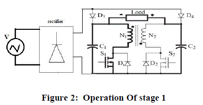
| The fundamental principle of the projected dc–ac flyback is based upon the application of the voltage difference between capacitor C1 and C2 to the lamp. Stage1: where C2 voltage is the summation of E and the load voltages, reverse biasing (blocking) D4. S1 conducts and S2 ruins opened. C1 voltage is applied to the flyback primary, N1. Thus, primary is exciting with energy squarely relative to the current throughout S1, supplied from C1. |
 |
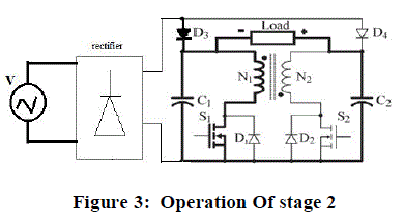
| Stage 2: When C1 voltage is identical to the voltage of the input voltage source E (C2 remain with lamp plus E voltages), at a standstill with S1 closed and S2 opened, voltage E is directly applied to the flyback primary N1. Ballast maintain to be charged, but with the energy from the voltage source E. |
 |
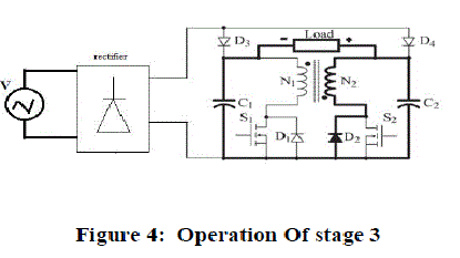
| Stage 3: S1 is open. The energy stored in the inductor is transferred to the electric field C2 through current flowing by the anti-parallel diode of S2, D2. |
 |
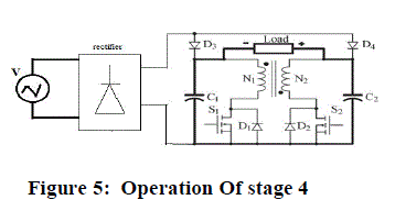
| Stage 4: S1 and S2 are kept in off position and there is no energy stored in the ballast. Current flows from capacitor (C2) to C1 through the load. |
 |
V. SIMULATION RESULTS |
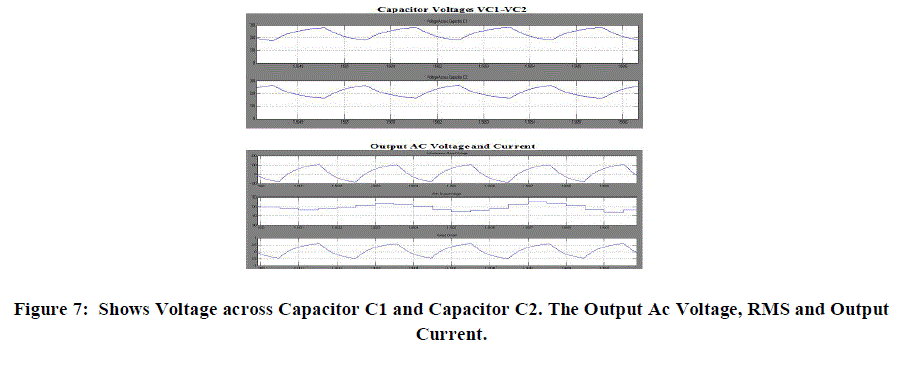
| In the projected system, the dc supply can be obtained by rectifying the standard AC supply. In adding up EMI filter can be included to prevent the interference of created at high frequency with 50Hz supply. The merits of the proposed system are extra power devices and passive components are not necessary.ZVS is obtained at resonance. Switching losses, conduction losses are significantly reduced and highly Efficient. |
 |
 |
VII.EXPERIMENTAL RESULTS |
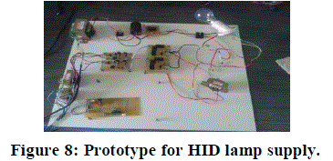
| The microcontroller performs all the necessary tasks during initial stage, warming-up, and steady state, including closed loop control of lamp current and protections. The microcontroller features are 256 bytes of EEPROM data memory, auto programming, an ICD, 2 Comparators, 8 channels of 10-bit Analog-to-Digital (A/D) converter, 2 capture PWM functions, the synchronous serial port can be configured as either 3-wire Serial Peripheral Interface and a Universal Asynchronous Receiver Transmitter (USART). All of these features make it ideal for more advanced level A/D applications in automotive, industrial, appliances and domestic applications. The design is the simplicity and the feedback loop has been digitally implemented according to the sensing unit. The positive voltage signal off the op-amp output is applied at the end A/D1, where the microcontroller performs the sampling in 8 bits mode at 10 kHz of sampling frequency.D3 and D6 have been inserted in the original circuit for lamp current measurement purposes and, together with D4 and D5, for preventing conduction of the anti-parallel intrinsic MOSFET diode. For that, D4 and D5. |
 |
| Block the conduction of the body diode, while D3 and D6 carry the fly back’s discharge currents (N1and N2). As the normal current through C1 and C2 is null (capacitors), the average current through the diodes D3 and D6 correspond, respectively, to the average discharge current through N1 and N2: the lamp negative and positive currents. The buffer is used due to noise and reliability issues and could potentially become unnecessary with an improved PCB layout arrangement. Voltage measurements are used for failures detection such as open load and input overvoltage, and for sensing vL, it is important for implementing the startup, warm-up, and power control. |
VIII.CONCLUSION |
| The Electronic ballast for impulsive a HID lamps with high frequency from a 230 main supply. Efficiency is the main factor for lamp applications; hence it decreases the power consumption and also increases the reliability of the output power. A simulation result obtained satisfies the analytical results previously presented. The converter model has been presented; in add-on the filter circuit utilized in order to reduce the undesirable noise signal. A high intensity discharge lamp (Sodium Lamp) using the concept of fly back converters is formulated with high power factor and efficiency. The simulation results can be achieved with feedback system. EMI filter (Electromagnetic Interference Filter) is added to prevent the interference of generated high frequency with 50Hz supply. The resultant of this work shows that envelope simulation can be used to incur the small signal output of a high frequency system. The validity of the simulation method was proven and exhibit simulation tool is reliable and simple to use. It is thus concluded that by applying proposed simulation and design methodology the performance of the operating system in closed loop configuration can be improved so the power factor and efficiency is enhanced. |
References |
|